Topic: Heated Bed Upgrade - Guide with Pics/Comparisons/STLs
Hi all,
been wanting to finalise and post this for a few weeks, but been very busy on the weekends. Slowly getting it up now.
Problems with the Standard Heated Bed
The main issue is the immense amount of time needed to heat the bed to a temperature acceptable for ABS adhesion. My printer was taking 10-15mins to reach 95 from cold, and I found I was leaving it on between prints to avoid waiting again. This meant for a 'printing' day at home, it would be sitting at ~100 degrees all day, not good for power bills or the environment.
Others have had problems with warped beds or screws sitting up proud, but mine was always fine.
Wiring and connectors are also an issue for both the bed and hot end, and I recommend upgrading them asap. I like these connectors, and recommend using something like them even if you are not upgrading:
http://www.jaycar.com.au/productView.asp?ID=PT4452
Power Supply Issues with Upgrading
The standard power supply can deliver about 10 amps maximum, with many bed upgrades drawing more than this. It is, therefore, important that the power supply is upgraded when upgrading the bed. A QU-BD silicone bed needs 12 amps, and others may need more. It's recommended that when upgrading you over-engineer and get a power supply that easily exceeds your needs.
I used a 12V version of the Makerbot Replicator power supply (which is 24V):
http://www.meanwell.com/search/gs220/default.htm
It wasn't cheap, but it had a tidy appearance and delivers a reliable 15A if needed. I've been using it for some months now and have had zero problems.
Sanguinololu PCB Problems
The next weakest link in the power supply system is the Sanguinololu board, which some pundits describe as underdone in the design of the heated bed traces. Some users install a solid state relay to switch on an upgraded bed to avoid drawing the greater current through the PCB, but I found it easier to make a couple of modifications to the board.
1. Jumper leads:
To beef up the capacity of the stock board, jumper wires were soldered as shown below. The MOSFET that switches the current is rated very high, so adding the jumper wires fixes the issue of too higher current and the board potentially overheating.

2. Upgraded terminals:
The terminals are also rubbish on the Sanguinololu. I upgraded the power supply and heated bed terminals at the same time to more robust units. Once again, just some quick soldering to remove the old and install the new.
http://www.jaycar.com.au/productView.as … ATID=991#1
http://www.jaycar.com.au/productView.as … ATID=991#1
http://www.jaycar.com.au/productView.asp?ID=HM3130

Selecting an Upgraded Bed
For this thread I've tested three solutions:
1. 'New' Solidoodle heated pad as fitted to newer models.
2. QU-BD 150mm silicone bed. http://store.qu-bd.com/product.php?id_product=36
3. Home made custom heated PCB: http://www.thingiverse.com/thing:65033/

Each were tested in the same way to make comparisons fair. The areas tested were:
-Speed of heating
-Distribution of heat across surface
-Ease of fitment
The following image depicts the setup I used for each. A thermistor was taped to the top of a sheet of glass and used for each test. This meant that the readings were directly comparable, and the thermistor built into the Solidoodle an QU-BD pads were not used. The same aluminium bed was kept in place for each test for consistency too. This and the glass were cooled between tests to the same low level.

Comparison 1: Speed of Heating
Straight 12V DC was applied to each heater to avoid PID or firmware issues, and the graph comparing the units is seen below. The Solidoodle replacement pad seems just as slow as the original heater block. In the graph the thermistor table was under reading by ~20 degrees C (but the same for all solutions), but I still gave up waiting for it to heat all the way to printing temp. The custom PCB and QU-BD pad are very similar and so far superior to the standard units it's ludicrous. In practice, heating up the bed is a few minute job, instead of a quarter of an hour. Note the similar curve in temperature due to the less than ideal QU-BD thermistor table I found googling.

Comparison 2: Distribution of Heat Across Surface
An infra-red laser thermometer was used to sample the temperature in the centre, half way out, and the corner of the glass. Whilst this may not be perfect, it was very consistent and fair. Temperatures are expressed as percentages of the centre reading to make comparisons easier.
The caveat here for the Solidoodle pad is that it stops considerably short of the aluminium bed edge, meaning no direct heating takes place on the edges. The QU-BD pad and custom PCB both match the bed size. The custom PCB was designed to have less heat in the centre by spacing the traces further apart in this area. Earlier iterations of the design were poor in this regard. The QU-BD pad still wins here, with more consistent heat distribution.
Tiny Solidoodle pad:

Heater             Centre          Half-way          Edge
---------------------------------------------------------------------
Solidoodle        100%           93%                 51%
QU-BD             100%           96%                 72%
Custom PCB        100%           94%                 67%
Comparison 3: Ease of Fitment
Obviously the Solidoodle solution requires no fitment, so trumps the others here. When I ordered a replacement aluminium bed, it came with the heating pad and insulation already in place. Fitment would just be a matter of unscrewing the three bed leveling screws, swapping and reassembling.
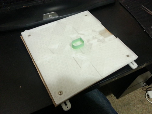
The hardest is the QU-BD bed, because the underside is uneven and bumpy where the wiring feeds in and the thermistor sits.

There are several options here: grind into the aluminium bed the extra clearance needed, fit a squishy spacer, or fit a rigid spacer with clearance for the bumpy bits. If you just wedge the bumpy silicone bed and clamp glass on top, it is likely to flex and break under heat:

I originally ground down the bed and made a mess of it. It still works but looks ugly and isn't really repeatable for anyone reading this guide.

I've just developed a printable spacer that should fit snugly. It goes together in four pieces and centers the silicone bed nicely. For a link and instructions please see later in the post.

The custom PCB can also use a spacer, but since there are minimal bumps on the underside, a flexible spacer is probably simpler to use.
Either the QU-BD or custom heated PCB will require the wire ends for the heater and thermistor to be prepped ready to connect to the Sanguinololu board.

In terms of firmware, the thermistor is different on the QU-BD bed, and support for this is built into my firmware. The thermistor table was found googling, and is a bit dodgy around 40 degrees as can be seen in my graph above. I contacted Solidoodle to ask them if the new heated pad needed a different firmware setting, and got a useless reply where the person didn't read my question properly and hence it was not answered. I've since discovered that there is a separate thermistor taped between the pad and the bed, and no firmware changes are required.
Solidoodle Silicone Bed Mounting Kit
Whichever solution you choose, you will likely want to use a glass bed above the heater. I have developed a clamping system which adapts to various thickness pieces of glass, offers a quick release system and requires minimal installation effort.
http://www.thingiverse.com/thing:64607/
The system requires four M3 screws, preferably with a counter sunk, hex socket head. It also needs some random screws with a wide head, and some springs that can be cut down to fit.
Included in the Thingiverse link is the four part spacer, smaller nuts to level the bed from beneath, and the two part glass clamping clips. After printing each part, all that should be needed for installation is drilling four 3mm holes through the aluminium bed in line with the holes in the spacer.
1. Print the large spacer parts (A-D). 10% infill is suitable. Assemble the spacer parts and drill four 3mm holes in the aluminium bed using the spacer as a template.

2. Print the remaining parts at >50% infill for strength.
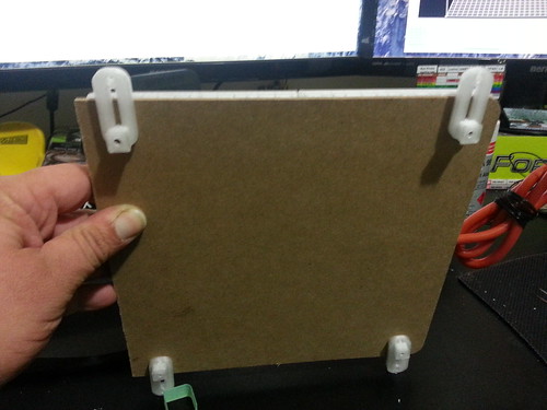
3. Insert the bed leveling screws through the aluminium bed and wooden carriage, before screwing on the bed height knobs. They should be a very tight fit.

4. Assemble four sets of the bed clip pieces as shown in the photo. I had some M3.5 screws with wide heads left over from something else. I also cut down some springs that were laying around.

5. Push a counter sunk M3 screw through the spacer and drilled holes in the aluminium bed. Line up the bed clip assembly and turn the M3 screw to cut a thread and attach it.
6. Place silicone heater or heated PCB on top and then a piece of glass. 160 x 170mm is ideal to get some clearance for the nozzle when homing.
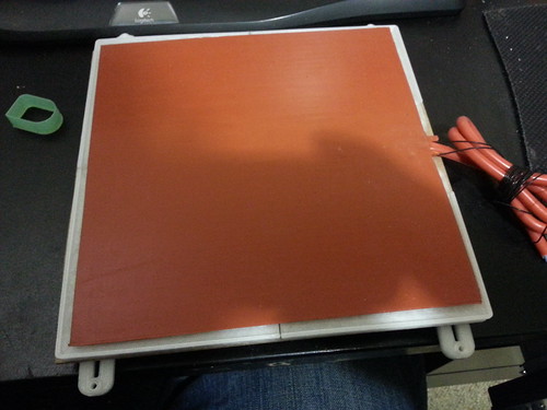
Bed mounting kit with QU-BD silicone bed:

Bed mounting kit with custom PCB:

7. Print! (but don't forget to set the z-height screw in a safe position to avoid cracking the now higher glass. Don't forget to alter the bed thermistor setting in configuration.h of the firmware if you haven't used the original. If changing to a faster option, you will find far greater performance by enabling bed PID temperature control in configuration.h on line 161. Flash the firmware, and run bed PID auto tune with:
M303 E-1 C4 S90This runs bed PID auto tune at 90 degreesC for 4 cycles. The log will spit out PID values when done. Change the PID values on lines 174-176 and re-flash the firmware after this.
Conclusion
If you are prepared to put in a bit of effort in the fitment, upgrading the heated bed is one of the most us user friendly mods you can make. It will be much, much faster to start prints, and using glass means you can have a continuous production line. I've ended up using the custom PCB simply because it's easier to get the glass to sit flat on top of it. The QU-BD bed has similar performance but is tricky to sit right. Perhaps taping or gluing it down would help?
I'd also like to note that I had a QU-BD unit recently fail. It started with intermittent failure to heat until I wiggled the cords going in, which gradually became more frequent until it died permanently. It's likely a loose connection, but since everything is sealed inside, fixing is difficult.
Happy printing!