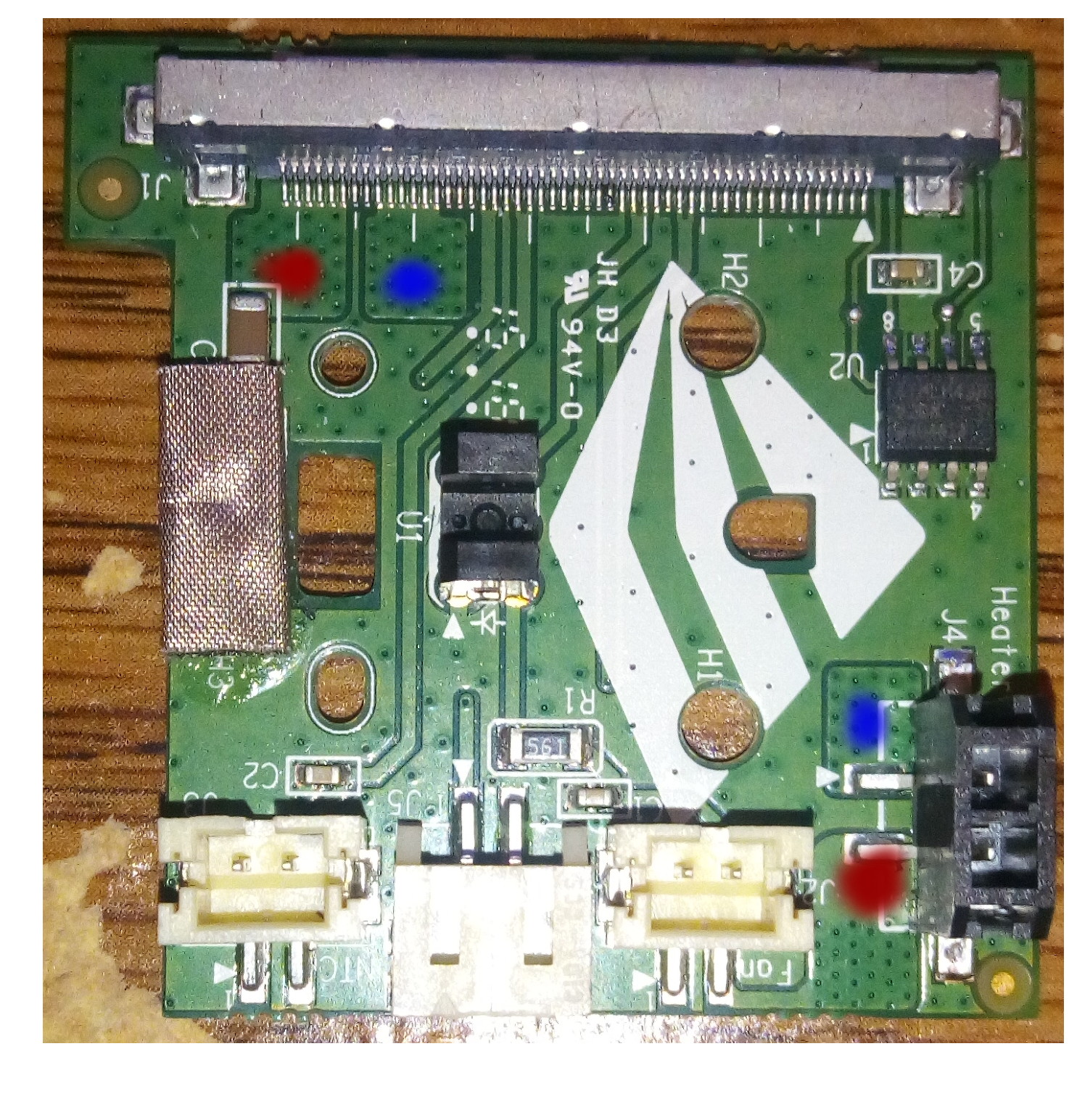
carl_m1968 wrote:Based on that last image, what are you calling a chip exactly. I thought you meant the small one marked U2. Your image and markings seem to refer to the ribbon cable connector along the edge of the board. If that is the case it is nothing but a friction fit connector for the ribbon cable. If you wanted to know the purpose of each pin you would need to connect the cable and trace back to the main board.
I should have clarified - the markings I provided are simply to the connection for the ribbon cable. The chip on the board is an ATMLH532, of which I'm still looking for information and a data sheet for.
Markings of that chip are as follows, the actual chip may vary from each:
ATMLH532
02DM Y
A2ANGA
EDIT:
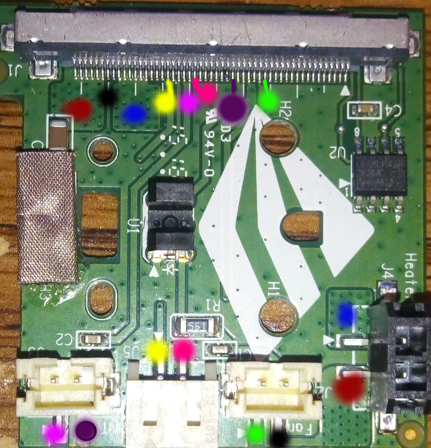
Assuming that the ground on the right of the cable connector is pin 1, with the only evidence I have being the ground on each header also happens to be Pin 1, I've made a simple cheat sheet to help in 2 things: First is to help confirm the pins I mapped, and second is to hopefully add to the pins that have already been discovered.
I grouped each pin to the white mark at every 5th pin, if that helps at all.
Header Header Pin Ribbon
------------------------------------------------------------------------
Fan (GRND) 1 16
Fan 2 45
------------------------------------------------------------------------
NTC (GRND) 1 30
NTC 2 22
------------------------------------------------------------------------
J5 (GRND) 1 34
J5 2 29
------------------------------------------------------------------------
Heater(GRND) 1 50
Heater 2 40
------------------------------------------------------------------------
EDIT #2: The ATMLH532 seems to be a power regulator. 12v 5a, which fits with the overall power requirements of the printer. Could be wrong, though.