Topic: [HOW TO] Da Vinci Mini Heatbed Conversion
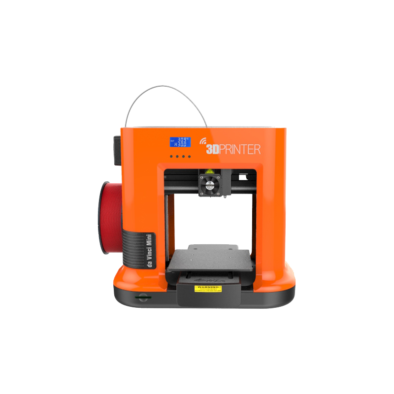
Showing how I added a heated build plate to my Da Vinci Mini W for posterity, in case any other poor soul stuck with this printer wants to attempt to try and polish this turd of a machine. I am running the most recent stock firmware, and only made cosmetic details to the mainboard.
This is what the end result looks like:
Before someone impulsively goes "ooh, that looks like a fun weekend project", here's why I would advise against doing this:
Without RAMPS or equivalent, you have to manually turn the heatbed on before printing, and off afterwards
There's a fair amount of soldering/crimping involved
Wiring around the mainboard is a pain, it' pretty cramped in there; and it's probably a fire hazard
I actually like XYZPrint's auto-calibration, but getting the glass clamped without obstructing the z-probe is nearly impossible
With a 3mm aluminum plate, 3mm peice of glass, and rising/leveling hardware, I'm sure the weight added to the Y carriage is non-trivial
Buying another cheap printer with a (probably larger) heated is only marginally cheaper
And so in what circumstances is this a good idea?
You don't want to replace the mainboard; which also means replacing the optical endstops for mechanical ones, as well as all the hotend wiring
You have a Da Vinci Mini or other version that has no Repetier port)
You're content with XYZ software (or now Cura support!)
You're stuck with one of these god-awful machines in stock setup with little recourse
You're fucking stubborn and determined to get your printer to make decent prints, without realizing the number of steps to make this happen (me)
Parts that I used (excluding wire, crimps, screws, etc):
160x160mm Aluminum Hotbed - https://www.ebay.com/itm/Aluminum-MK3-1 … 4412985216
10K ohm Glass bead thermistor - https://www.ebay.com/itm/2pcs-THERMISTO … 2809661914
165x165x3mm Glass Plate - https://www.ebay.com/itm/165mm-x-165mm- … 2587585558
350mm 2020 Extrusions - https://amazon.com/gp/product/B07QXPF9GH
12V 30A Power Supply - https://amazon.com/gp/product/B010CVIW6K
DC Temperature Control Board - https://amazon.com/gp/product/B07GQPT9VG
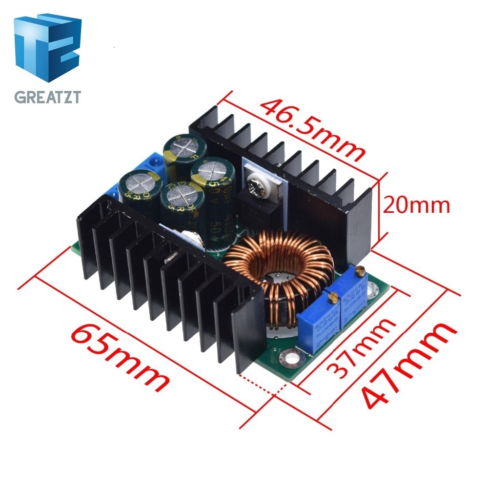
Boost Converter - https://amazon.com/gp/product/B00J1X
M3 Thumbscrews - https://amazon.com/gp/product/B07LFSNNSK
250V Switch and Power Socket - https://amazon.com/gp/product/B00NWLE4U6
Silicone Bed Risers - https://amazon.com/gp/product/B07RZKF8MB
All the power comes from the new 12V power supply, so the transformer that came with the printer can go in the parts bin.
I wanted to be able to disconnect the power supply, so I butchered a powerpole cable and printed a mount where the power rocker used to be (there's a main switch on the power supply, so I just clipped the rocker terminals and shorted the pins with a bit of wire. The 12V comes in and is spliced to the heat bed controller, 12V layer fan, and the boost converter with appropriately gauged wired. 24V coming out the boost converter is soldered to where the barrel plug (for the old transformer) used to be (I just snipped that as well).
Here's what the back looks like now:
Everything else is pretty straightforward wiring and mounting the new heatbed. I drilled holes in the stock aluminum plate to function as the Y carriage plate. It's pretty heavy, so I might want to saw off some chunks in the future for the Y motors sake.
Complications I Encountered
You may have noticed that the parts list included extrusions...well moving the bottom of the Y axis up ~20mm, without any ability to tell the printer otherwise (stock firmware), means the whole X assembly crashes into things. So the worst part of this build is definitely having to remove all the hardware to replace the stock Y extrusions for a measly extra 20mm. Note back in the mainboard picture where I had to drill through plastic to get at the retaining screws (I was getting frustrated and didn't want to dismantle the entire Y carriage assembly). Luckily the Z screw is long enough, because I have no idea how to get a longer one.
Another painful realization was that the digital temperature controller expected a 10K NTC thermistor; so the readings with the 100K one soldered to the bed were way off. Luckily I found some tiny, 10K, glass bead thermistors on ebay. The power curve is close enough to what the controller was expecting, so the readings are more than acceptable for a heat bed (within a couple degrees at worst).
Make sure you print a Z-riser first, or you'll have to rig something together with springs like I did.
Also make sure you get the tiny, little thumbscrews for bed leveling. They're a pain to actually use compared to those beefy wheels, but you'll need the clearance on the underside of the carriage.
120V live wires hurt.