Topic: Replacing the Z axis
Since I got one of the first printers, mine shipped with the original z axis coupling between the motor and lead screw. When Solidoodle changed the design, they were kind enough to send out the replacement to me, but I was hesitant to replace the original since it seemed to be working, albeit with some exaggerated z wobble on the high res prints. As these things usually go, the coupling failed/cracked when I was in the middle of a long run of prints for the RObot project that had to be done in a hurry. In addition, the thermistor wire failed, which I will post about replacing shortly. Anyways, replacing the z axis motor/leadscrew can be very easy; however, it is a good opportunity to do some maintenance on some parts you wouldn't normally think to get to. We also need to find a way to conquer the banding here soon, and this process is good to understand fully when attempting solutions to that problem.
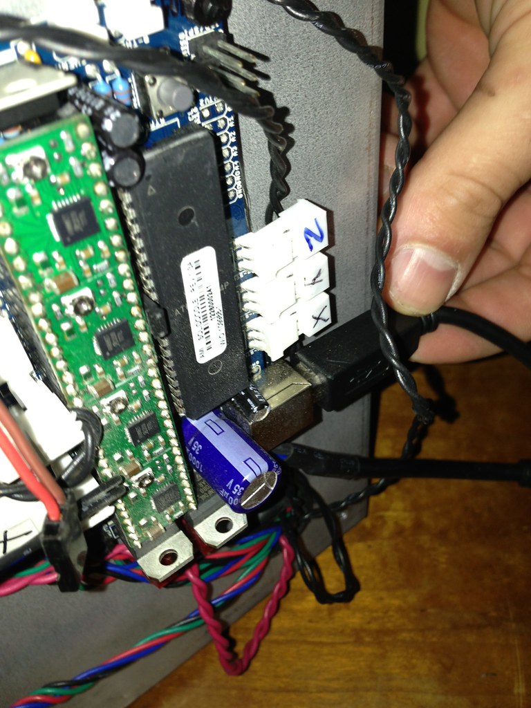
The first step is to remove the usb cable so that you don't accidentally tear it out during the process...
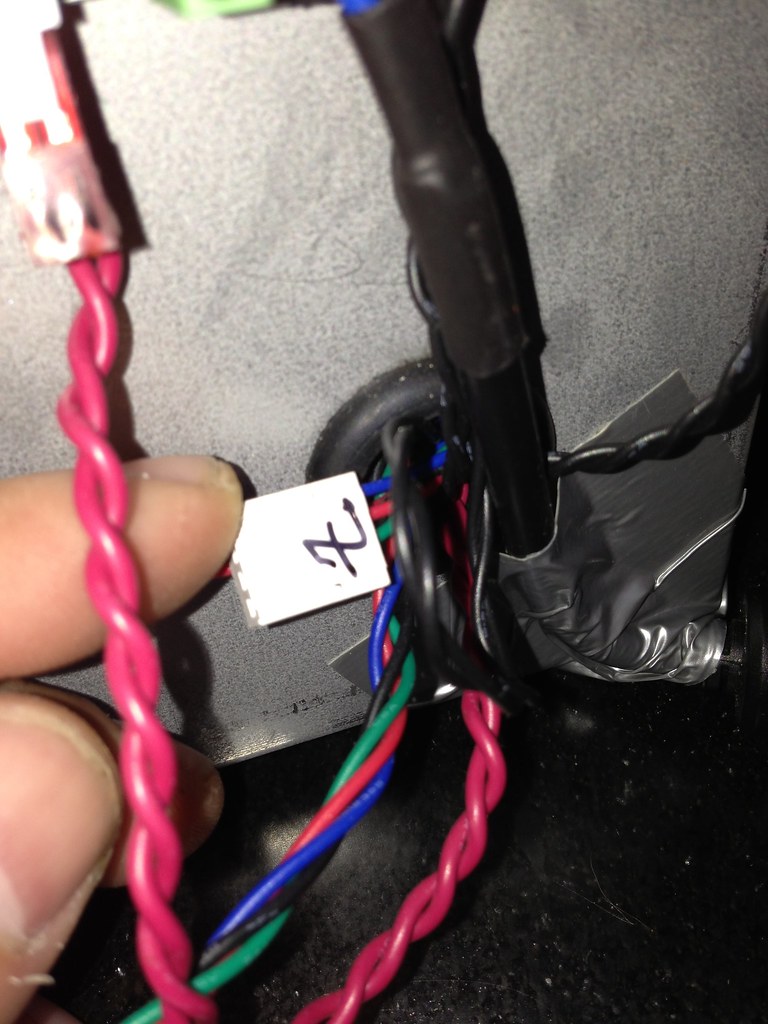
Next, since I was going to be moving the printer around a good bit, I took the time to duct tape the power cord to the corner of the printer. This is a good way to add some strain relief and once it is done, you shouldn't have to worry too much about yanking out the power supply any more.

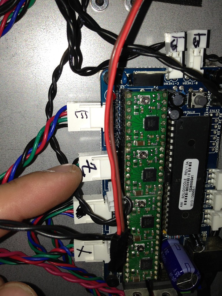
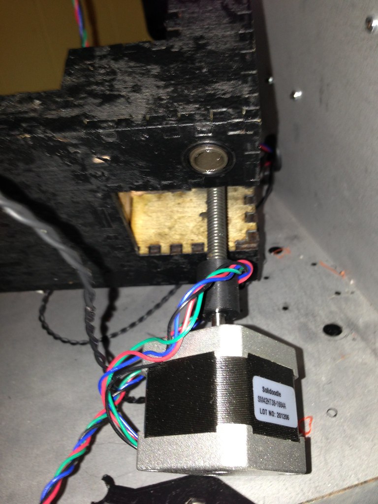
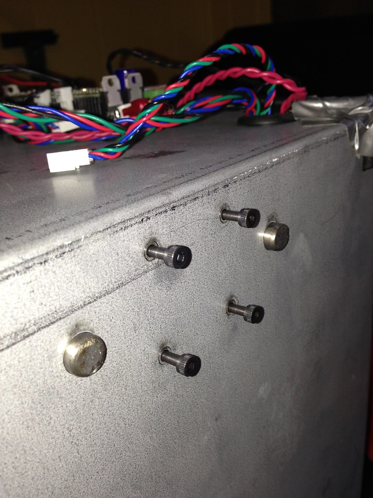
Now, find the z motor connector and remove it from the board. It is located here:
Next, pull the wire through the hole in the bottom of the printer...
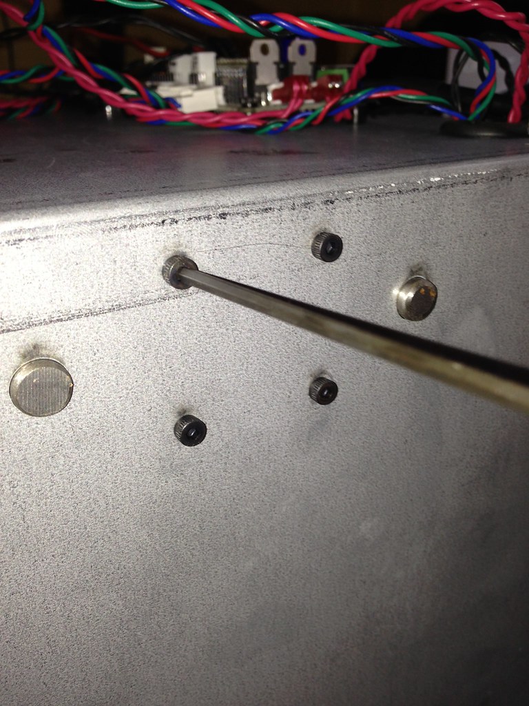
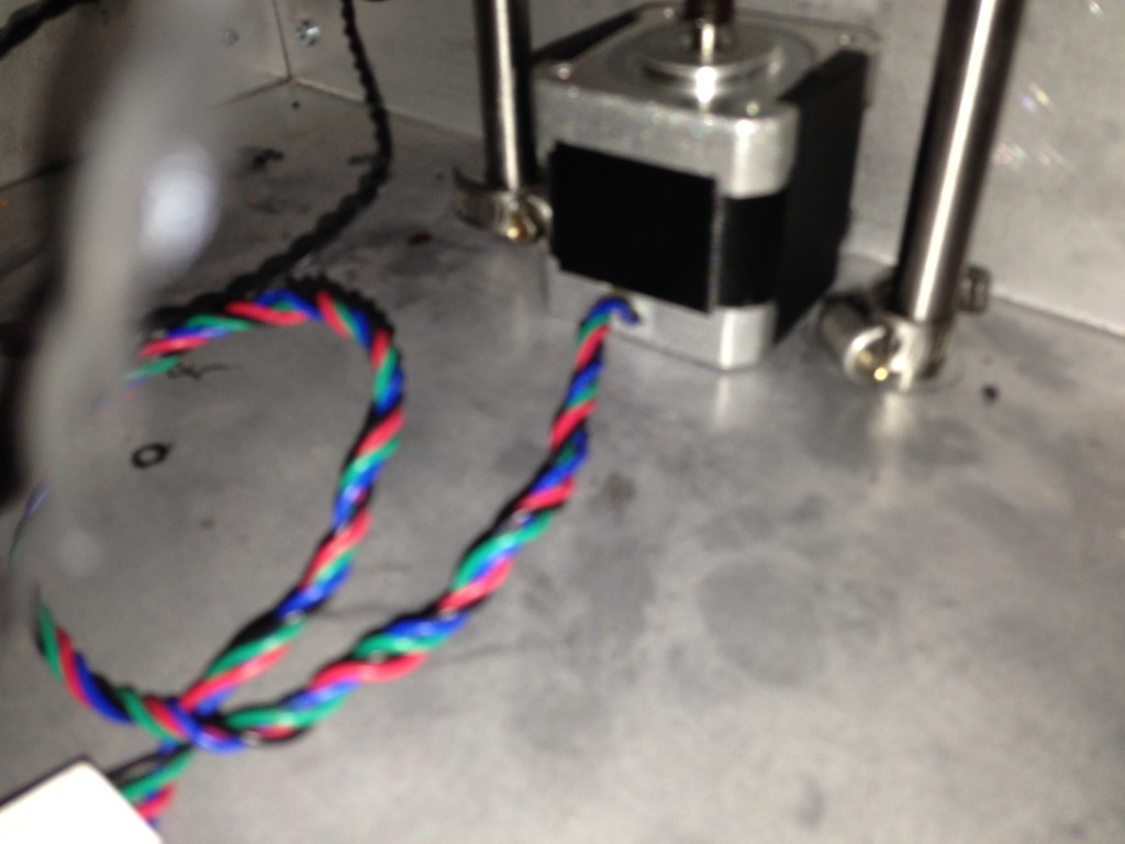
Now turn the printer so you can access the bottom and remove the 4 screws connecting the bottom motor.
Now you need to loosen the 4 hose clamps keeping the guide rods for the z axis in place. There are two on the top and two on the bottom.

Once all the clamps are loosened, you can remove the guide rods and the printer bed should be free to move around.
Remove the leadscrew and motor by rotating it out of the nut for the bed.
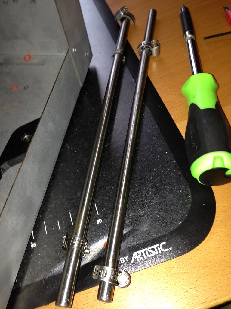
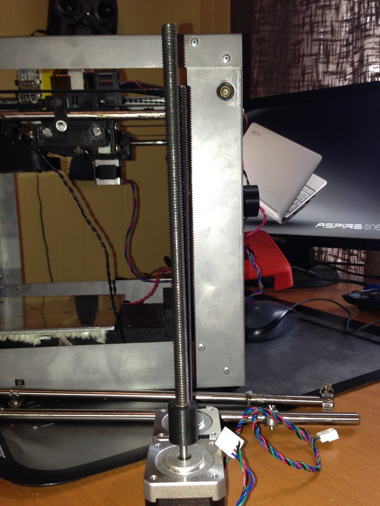
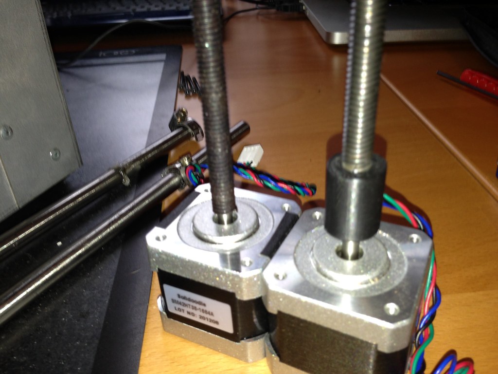
Here are some comparisons of the two motors/leadscrews. The original assembly is clearly taller and not straight at all. From the side view with a straight background, you can see the shaft leans out quite a bit more than the new one.
I do wish, however, they kept the new design taller. It allowed for a lot better system to control the slop in the x axis with the reinforced bearing Ben Trigg and Ian designed way back in the beginning. This piece will no longer fit since the new leadscrew only comes up to the cross rod for the y axis in the back instead of well clear of it. Here is a picture showing the coupling for the old and new systems. The old system was a printed abs coupling and it was prone to wear and tear. The other problem was that the shaft was not perfectly centered or perfectly vertical.
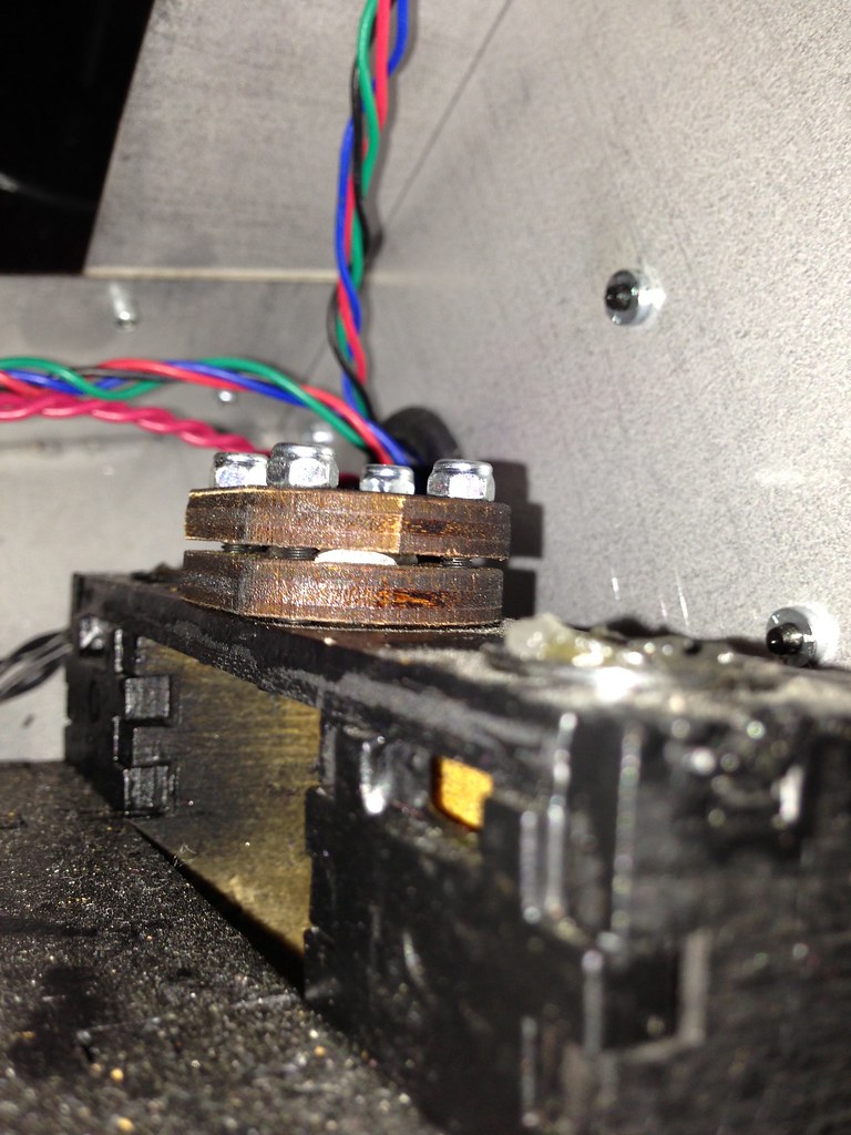
This is a good time to check that the net and the nut hugger? are bolted in tight. As an aside, John from Solidoodle has mentioned that they are soon going to come out with a complete schematic that actually names everything. It will be quite a relief since it seems every part has 30 names now. Anyways, back to the nuthugger. Mine was loose to the point you could actually hear the nut shaking around on the inside. I tightened it down very firmly, but was careful not to go so tight that the wood might crack. This should help with the play in the z axis and possibly a little in the x axis.
This is also a good time to go ahead and lube everything up. I actually cleaned everything very thoroughly and then lubed. I use this stuff since it is cheap and easy to get at my local hardware store.
http://www.amazon.com/gp/product/B000XB … 07_s00_i00

The rest of the process is pretty much everything in reverse order. There are a couple of things to be careful about when reversing the process. I threaded the leadscrew in about 1/2 way before reassembling. Then I put in the guide rods and just lightly tightened the hose clamps so they would not slide around while reattaching the motor. When putting the motor in, make sure your wires are coming out towards the front. Also make sure that you tighten each screw just a little bit before completely securing all of them, other wise you may end up with a bent screw.
That should about do it. One last thing, it is also a good time to check the stepper drivers since you replaced the motor. It shouldn't change anything, but it is still a good time to do it. The tutorial can be found here:
http://www.solidoodle.com/how-to-2/troubleshooting/
Any other suggestions are great.