1

Topic: Lighting the scanned object

Something I've been struggling with a little is finding the right level of ambient light for the scanner. It looks as though the Pi camera is doing some amount of adjustment to deal with different light levels, presumably something that it handles automatically, but there's definitely a range where it wants to be. Too dark and it can't pick up the color of the object; too bright and it doesn't see the laser lines. The sweet spot may be different depending on the object, too, but I don't have enough experience to tell for sure. Variations during the scan lead to different colored areas or stripes.

I've bought parts to add variable-brightness LED lighting to the scanner, controlled by the Pi, but haven't had time to put it together yet. Has anyone else run into this, and come up with a solution?

2

Re: Lighting the scanned object

Not Yet as, I don't have the Atlas 3D  yet,  But I'm sure it is a key point as well,  can you told me what  Led driver did you buy ,

then I can make some test as well, I suggest you to get a Luxmeter as well. to check the light arriving on the object

3

Re: Lighting the scanned object

I bought a meter of Dotstar LED strip from Adafruit.  It's not ideal since the best I can do is make white-ish light by turning on all three RGB LEDs at once; I really wanted to get the Dotstar white LEDs but they were out of stock on the breakout boards and I didn't feel up to making my own. So I'll at least get started with a couple pieces of the strip, and can always convert later.

I have a couple of breakout boards with 74AHCT125 chips on them; I'll need to rewire because they were designed for NeoPixel strips, but it should be straightforward to use them with Dotstars. The 12 volt bus on my power supply should have more than enough capacity to drive a few LEDs too.

I'm building my own HAT board for the Pi 2 to hold the stepper driver, ULN2003A for the lasers and a voltage regulator, and the most challenging thing will be finding real estate on the board to add the 74AHCT125...

I was wondering about the possibility of including a light sensor, either mounted on the camera tower and pointing at the object or mounted just under the edge of the turntable, so I could try to keep the light level constant. I've already had one scan that turned out very strange-looking because the sun was setting behind a tree and the light level in the room kept changing!

Post's attachments

striped_scan.jpg 50 kb, 1 downloads since 2015-03-19 

You don't have the permssions to download the attachments of this post.

4

Re: Lighting the scanned object

Here's my scanner setup for my matterform scanner:

http://home.comcast.net/~tomhorsley/har … %20Station

I've got some white LEDs on a variable current controller module so I can adjust the brightness.

And these 3D printed pointy things to stick Styrofoam hemispheres in front of each LED :-).

http://home.comcast.net/~tomhorsley/har … ointy.html

5

Re: Lighting the scanned object

I was thinking of adding LEDs around the top near the edge the rotating base so I can ensure I have more consistent lighting.  My hope is that I can drive these from the Pi.

6

Re: Lighting the scanned object

fmotta wrote:

I was thinking of adding LEDs around the top near the edge the rotating base so I can ensure I have more consistent lighting.  My hope is that I can drive these from the Pi.

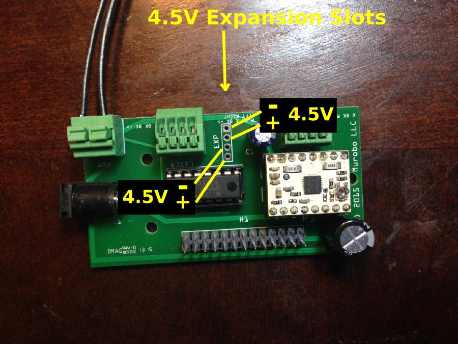
I added support for expansions such as these into the final PCB design.  It allows you to control two 500ma 5V devices from the Raspberry Pi in addition to what is used by ATLAS 3D itself.  You will need to solder a 4x1 0.1" pitch header on the PCB yourself if you want to take advantage of this.

7

Re: Lighting the scanned object

hairu526 wrote:

I added support for expansions such as these into the final PCB design.  It allows you to control two 500ma 5V devices from the Raspberry Pi in addition to what is used by ATLAS 3D itself.  You will need to solder a 4x1 0.1" pitch header on the PCB yourself if you want to take advantage of this.

Sounds like a nice addition - are you using two more of the pins on the ULN2003A?

8

Re: Lighting the scanned object

owens-bill wrote:
hairu526 wrote:

I added support for expansions such as these into the final PCB design.  It allows you to control two 500ma 5V devices from the Raspberry Pi in addition to what is used by ATLAS 3D itself.  You will need to solder a 4x1 0.1" pitch header on the PCB yourself if you want to take advantage of this.

Sounds like a nice addition - are you using two more of the pins on the ULN2003A?

Exactly.  It seemed a waste not to make some of them available.

9

Re: Lighting the scanned object

FWIW,  I just set my Atlas 3D.   I had lighting issues as well.    I put the scanner inside one of those popup 18" light boxes that they sell for people to use to make decent ebay photos.  So it turns all the direct lights in my workspace into ambient light.    It works pretty well so far.   I'm scanning TINY objects, so it's all calibration issues for me.

10

Re: Lighting the scanned object

hairu526 wrote:
fmotta wrote:

I was thinking of adding LEDs around the top near the edge the rotating base so I can ensure I have more consistent lighting.  My hope is that I can drive these from the Pi.

I added support for expansions such as these into the final PCB design.  It allows you to control two 500ma 5V devices from the Raspberry Pi in addition to what is used by ATLAS 3D itself.  You will need to solder a 4x1 0.1" pitch header on the PCB yourself if you want to take advantage of this.

Uriah, can you elaborate on this?  (Or point me to somewhere where the pinouts on the board are listed?)

I'm going to try and power a few DotStar LEDs with a hardware SPI interface to the Pi.  (To adjust color and brightness.)  I suppose I can provide external power and tap into the SPI pins on the PI through a level shifter to 5V, but I'm wondering if there's something to be gained by using these pins you've built in for power.

Thanks,

Byrom

11 (edited by n2ri 2016-01-13 22:36:29)

Re: Lighting the scanned object

being lasers are used to illuminate object for camera, I would think any other stray light is just likely to cause ill effects/reflections and a darkroom type enclosure would be a better idea plus blocking any other light even from LEDs from interfering with scan. I am planning to do just that with mine. we are not taking color photos after all. just a 3D contrast image with sharp edges for detail.

Solidoodle 2 with Deluxe kit cover & glass bed with heater. and 2nd board SD2 used not 3rd and alum platform not installed yet still wood. also need cooling fan installed to board. use Repetier Host couple vers. Slic3r also have all free ware STL programs

12

Re: Lighting the scanned object

What information do you need on it?

Byrom wrote:
hairu526 wrote:
fmotta wrote:

I was thinking of adding LEDs around the top near the edge the rotating base so I can ensure I have more consistent lighting.  My hope is that I can drive these from the Pi.

I added support for expansions such as these into the final PCB design.  It allows you to control two 500ma 5V devices from the Raspberry Pi in addition to what is used by ATLAS 3D itself.  You will need to solder a 4x1 0.1" pitch header on the PCB yourself if you want to take advantage of this.

Uriah, can you elaborate on this?  (Or point me to somewhere where the pinouts on the board are listed?)

I'm going to try and power a few DotStar LEDs with a hardware SPI interface to the Pi.  (To adjust color and brightness.)  I suppose I can provide external power and tap into the SPI pins on the PI through a level shifter to 5V, but I'm wondering if there's something to be gained by using these pins you've built in for power.

Thanks,

Byrom

13

Re: Lighting the scanned object

Uriah,

I'm presuming there are holes on the Atlas board where I can solder a 4x1 0.1" header to access the pins you were talking about (to control 5V/500ma devices from the PI through the Atlas board).  I'm not sure which holes those would be or which pins are which?  How they would relate to PI GPIO pins, for example.  Which pins are data/ground/power?

Where should I solder the header?

I haven't been able to find a schematic or layout of the board (maybe I'm not looking in the right places).  For what it's worth I was a kickstarter June full kit supporter.

If these things are obvious, then I'm sorry that I haven't been able to figure this out myself....

Thanks for any help,

Byrom

14

Re: Lighting the scanned object

Uriah,

I think I found the Eagle files for the Atlas PCB design.  If so, then I'm probably all set.  (I can't view them from where I am right now to make sure.)  Hopefully they've got your change where you exposed the extra pins from the ULN2003A to headers.

Anyway, I'm hoping that'll answer my questions...

Thanks,

Byrom

15

Re: Lighting the scanned object

Byrom,

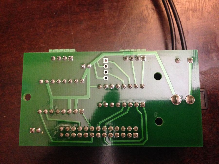
If you've found an Eagle file then it's not the design used in ATLAS 3D.  The picture below shows the ATLAS 3D PCB with the expansion ports.  The pins are outputted from the ULN2003A so some voltage is dropped resulting in 4.5V.  When the ribbon cable is hooked up to an ATLAS 3D, the two outputs can be triggered via the RPi pins.  I don't recall which but can look it up later.

http://soliforum.com/i/?d4lFKG6.jpg
http://soliforum.com/i/?CRt8GmR.jpg
- Uriah

16

Re: Lighting the scanned object

Uriah,

Thanks very much for the information and the pictures.  It's painfully obvious now that I should have figured this out myself.  (I didn't take my Atlas apart and look at the board.)  You might take some pride in the fact that I'm going to use those pins, though, to power my LEDs.  So your extra effort was not in vain.

And it looks like the SPI data and clock pins are free, too. 

For anyone else's benefit, I'm reading that the PI GPIO pins that control the two expansion header pins are GPIO13 and GPIO15.  15 is the one closer to the edge with the square pad.   (I still need to verify that with a test, though.)

My Atlas3d is working great, and I expect it'll be even better when I get consistent lighting and adopt more of yours and Pirvan's advice from this board.

Thanks very much!

Byrom

17

Re: Lighting the scanned object

Just for anyone who's curious:

I got native lighting to work with the expansion port for power and hardware SPI to set colors/brightness.  I should clarify that the expansion port is hardware pins 13 and 15, GPIO2 and GPIO3 (WiringPI), BCMGPIO 21or27 and 22.  So you can control it like this:

gpio mode 3 out
gpio write 3 1        (to enable 4.5v)

I soldered wires onto the bottom of the board at PI pins 23 and 19 for the SPI clock and data out.  Put those through a 74AHCT125 (as suggested by Adafruit docs for DotStar LEDs) and eveything works now, all self-contained in the Atlas 3d.

18

Re: Lighting the scanned object

so why do you want to light up scanned object and creat stray reflections to have to filter out of scan? laser scanners do not need it as camera is not doing a color photo scan. thats a whole different type scan system and not as detailed

Solidoodle 2 with Deluxe kit cover & glass bed with heater. and 2nd board SD2 used not 3rd and alum platform not installed yet still wood. also need cooling fan installed to board. use Repetier Host couple vers. Slic3r also have all free ware STL programs

19

Re: Lighting the scanned object

Um, I'm not sure how to answer that.  I don't think it's doing what you think it's doing.  Do you have yours working yet?

The lasers are just projecting a line onto the object and the shape of the line from the camera image tells the scanner where to "place" the (color) pixels of the object image in 3D.  So, yeah, it is a color scan. 

It's easy to find scanned color models in the example pictures on this board.  In my opinion, Pirvan's write ups here on getting a good scan and post processing are very good, so look for those when you do get started.

20 (edited by n2ri 2016-01-17 20:42:48)

Re: Lighting the scanned object

also saw lots of issues with stray light causing objects in mid air to need removed from scans afterwards, this is glare of some light spectrum's which interfere with the laser light waves  sun and incandescent being the worst. this is why when using say an laser temp prob sunlight makes it not work like infrared remotes etc. and best reads are on flat black objects that absorb most light which makes red/ruby laser light easier to read by camera also. also light filters can be used for specific light spectrum elimination. this is why when you look up early laser scanner projects they done the scans in dark room type conditions close as possible. scanning an object for creating a 3D file is all about fine definition contrast like black and white film.

Solidoodle 2 with Deluxe kit cover & glass bed with heater. and 2nd board SD2 used not 3rd and alum platform not installed yet still wood. also need cooling fan installed to board. use Repetier Host couple vers. Slic3r also have all free ware STL programs

21

Re: Lighting the scanned object

also you want to dull anything around the laser so reflections are not created when laser light hits it especially parts of scanner which are not even being scanned some times object being scanned can also reflect stray laser light so dull coat may be used if model is able to to be painted or dulled down reflective surfaces. you will see this mentioned in several 3D scanning videos/tutorials.

Solidoodle 2 with Deluxe kit cover & glass bed with heater. and 2nd board SD2 used not 3rd and alum platform not installed yet still wood. also need cooling fan installed to board. use Repetier Host couple vers. Slic3r also have all free ware STL programs

22

Re: Lighting the scanned object

with a plain photo 3D scan method lasers are not even used but regular room or bright lights then full color images are spliced together and with that wide of color saturation range you loose some fine definition making for lower resolution details. these differances are why the camera resolution makes less differance in laser scanners but still does help for better fine details with laser scanning if focused good and narrow laser line used. this all adds up to why the Atlas Scanner is better than Makerbots at lower cost too.

Solidoodle 2 with Deluxe kit cover & glass bed with heater. and 2nd board SD2 used not 3rd and alum platform not installed yet still wood. also need cooling fan installed to board. use Repetier Host couple vers. Slic3r also have all free ware STL programs

23

Re: Lighting the scanned object

The ATLAS 3D scanner can combine the laser data and the camera color data to produce full color 3D reconstructions.

Hence, lighting the object appropriately is important in order to capture full color, 3D scans like this:

http://www.soliforum.com/misc.php?action=pun_attachment&item=9153

24

Re: Lighting the scanned object

elmoret wrote:

The ATLAS 3D scanner can combine the laser data and the camera color data to produce full color 3D reconstructions.

Hence, lighting the object appropriately is important in order to capture full color, 3D scans like this:

http://www.soliforum.com/misc.php?action=pun_attachment&item=9153


but why? can it make a full color STL file for a full color 3D printer?

Solidoodle 2 with Deluxe kit cover & glass bed with heater. and 2nd board SD2 used not 3rd and alum platform not installed yet still wood. also need cooling fan installed to board. use Repetier Host couple vers. Slic3r also have all free ware STL programs

25

Re: Lighting the scanned object

STL files don't have color data so it'd be a different file type, but yes. Also to import to 3D modeling software for say, a video game.