Re: deformation test
Added a picture to above.
You are not logged in. Please login or register.
SoliForum - 3D Printing Community → ATLAS 3D & FreeLSS → deformation test
Added a picture to above.
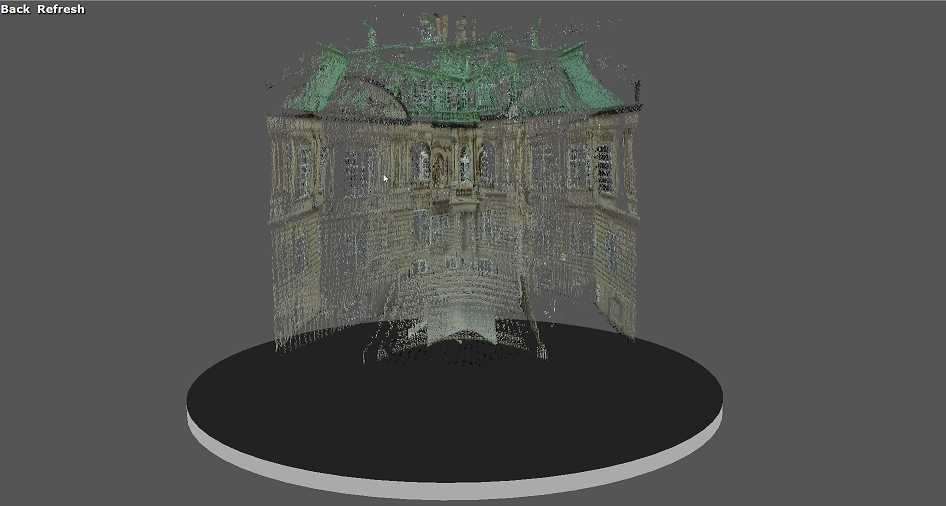
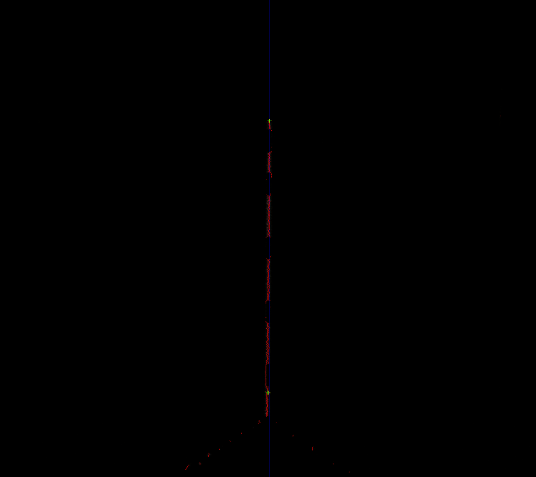
This is as seen in program after scan,
and scanned with both laser and with default setting.
Would offcause be much better with High Quality, but for this thread
i just did a quickie.
As you can see, the small white box below the model, also get the imploding look,
so size doesn't matter, as i thought.
Tried a little cat statue.
Can easy see the similarities ![]()
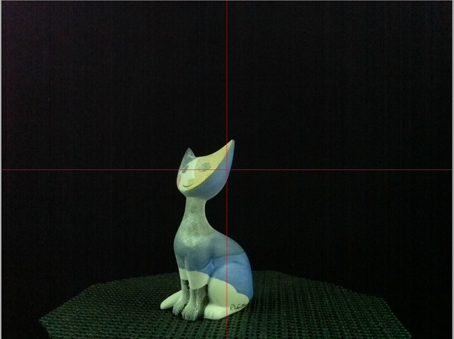
This is after a calibration: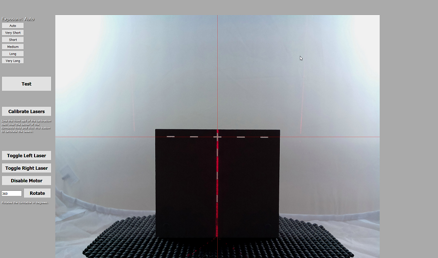
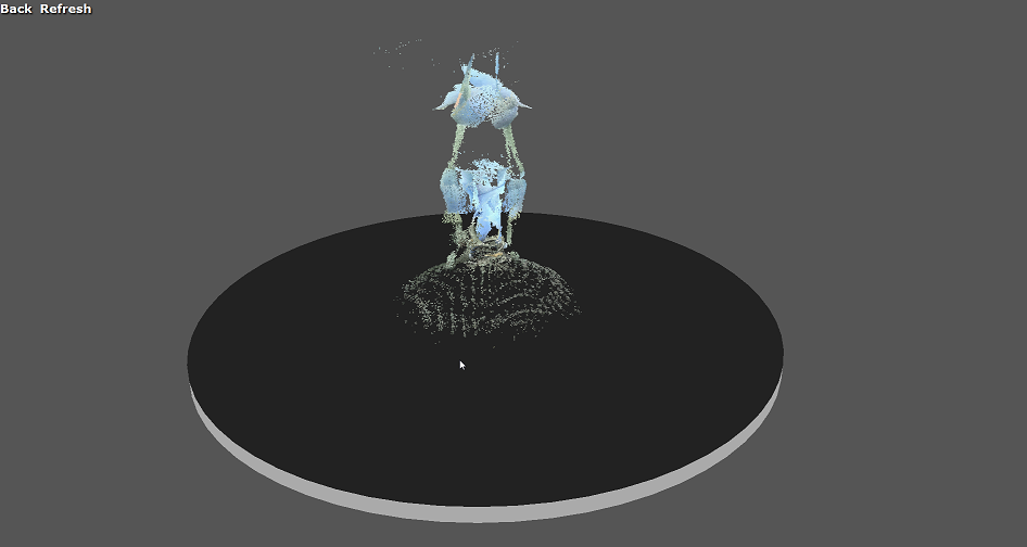
Here i made the little cat in High Quality,
still looks like its atop a small hill.
Screeshots from Meshlab, had to remove alot of noise before posting here.
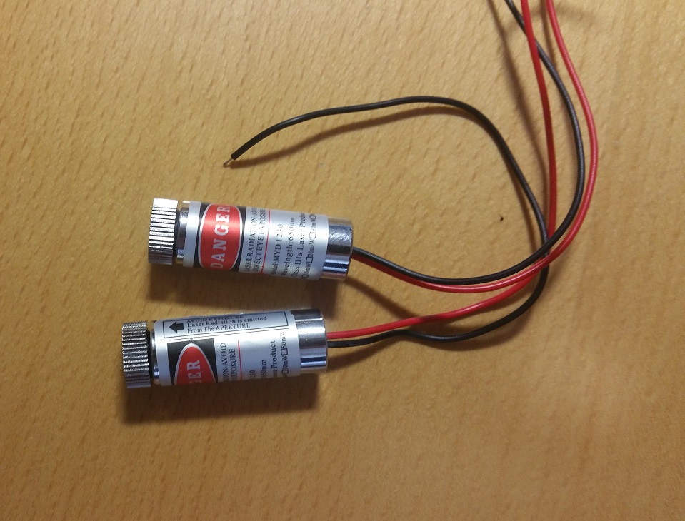
Just became father for these two babies ![]()
They cost 35,- Danish kroner each, its like 5.28 $.
Not that it will help my problem, but hopefully
it will be solved with time.
I hope someone will come with a solution to my above problem ![]()

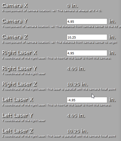
Can you post a snapshot of your camera/laser settings (similar to the snapshot knowack posted above) ?
You need to measure the actual distances of the left and right lasers from the center of the camera lens, and enter those numbers in the settings. Do not rely on the default values.
Here you are.
The distance from each laser to camera is ok.
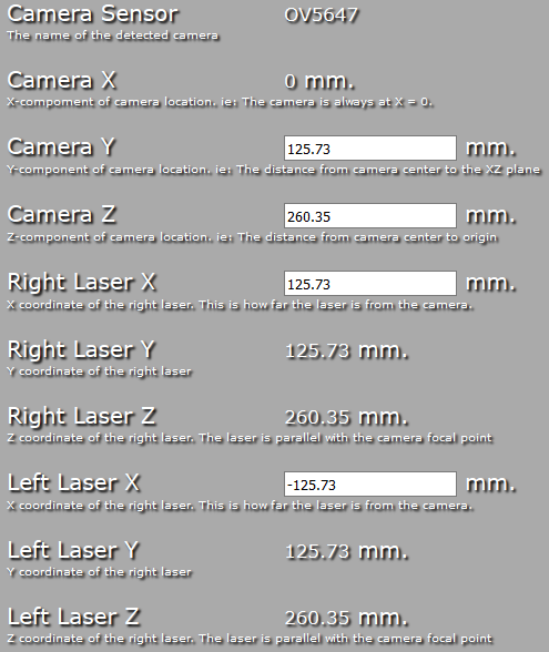
Oh and here the camera name detected:
And for those like myself, who likes metric system:
The camera Y position looks strange. That is the height of the center of the camera lens, as measured from the top of the turntable. For most of us that built the original scanner, with the printed parts, that value is about 3.25" to 3.5", not 4.95". That value also determines the height of the lasers, since they are supposed to be inline with each other.
Can you verify the height of your camera and lasers?
Here is a link to my settings. They are from an older version of FreeLSS (1.14), but they worked great for me. You might want to compare and see if it helps with your issue:
http://www.soliforum.com/post/113049/#p113049
Ahh... I didn't dare to change any values, since i didn't know what they represented.
But Camera Y should then be 3.50394 in. instead.
and Camera Z should be 10.5118.
Right and Left laser X is correct.
Will try with these numbers...
4.95" is definitely not the correct Y value. You can click the Restore Defaults button to bring the settings to their default values if you are not sure what you changed. After any Settings change, don't forget to setup the calibration item and click Calibrate Lasers again.
- Uriah
Camera Y, Right Laser X, and Left Laser X are all wrong.
Take a look at post #19 of this thread for known good settings.
Camera Y, Right Laser X, and Left Laser X are all wrong.
Take a look at post #19 of this thread for known good settings.
Here is a link to the exact post knowack is referring to.
http://www.soliforum.com/post/133437/#p133437
The values for the camera settings should match the actual measurements. Depending on how the scanner was built (printed parts, precut plywood, home made, etc), those values will differ.
Assuming one built the printed version correctly, their dimensions should be the same as the default settings, but then again, there are always variations, that's why it's important the values match the actual measurements.
Sorry for the delay, but it got late here last night.
Different timezone : gmt+2.
I measured it all, and it was camera Y there was wrong, all the other
settings is good.
And its calibrated again.
And as you can see, the square isn't "square" ![]()
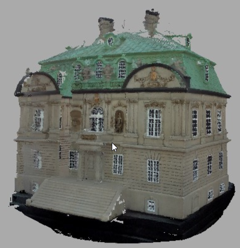
Here is last scan:
The building i tried earlier to scan, still looks the same.
And it seems that the ends gets cut off.
Since the building only have a size
of 130mm x 120mm, it should be scanned alright.
Is this an acrylic frame?
If so, stop measuring. Set the parameters to the numbers indicated in previous posts.
It is the acrylic kit.
I have dismantled the scanner completely, since i had to change the lasers to my new babies.
And the turn plate, need a firm hand to make sure it wasn't that to make the troubles ![]()
I will return when all is assembled, and finished first scan.
(I sincerely don't hope i happen to highjack someone elses thread, then pls say so, and i will
make a new thread, with my scanner problem:) )
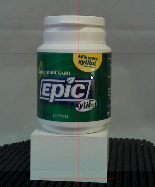
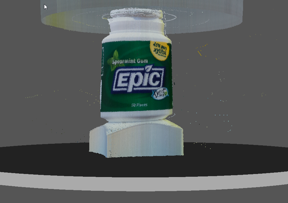
The problem may be your light source. If you are scanning with your lighting set up the same as in your preview then the scanner is seeing that shadow at the base of the bottle as a curve you need equal lighting from both sides or straight from the cameras view. Shadows will cause all kinds of issues with scanning.
There also seems to be a light source above and behind the scanning area as well. Looks to me like the focus on your camera is too far back and it sees too much of the area around the object.
From what I found with my scanner the focus of the camera should only see from edge to edge of the turn table. That also limits height to the same width as the turn table.
It is the acrylic kit.
(I sincerely don't hope i happen to highjack someone elses thread, then pls say so, and i will
make a new thread, with my scanner problem:) )
I think your problem seems relevant to the original subject, no worries. It turned out to be dimension settings for them too. Once you get your Atlas3D up and running, you'll be pleased with what it can do! There's lots of good info for it in these forums.
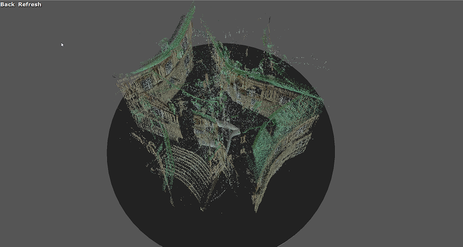
New update...
I dismantled my Atlas 3D completely, and when i assembled it again, i was wondering where left/right laser had to be.
Was it left as seen from turntable or from camera....
First time i thought it had to be seen from turntable...
Now i know its seen from camera... Oh well.... Shame on me. (To my defense, English isn't my mother language)
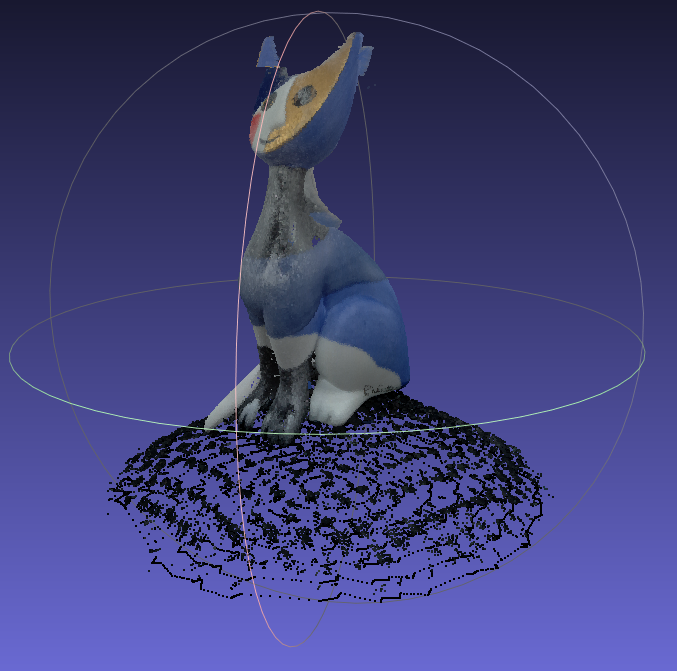
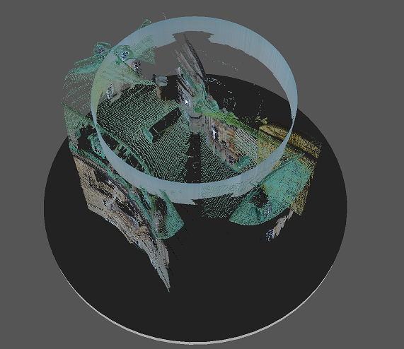
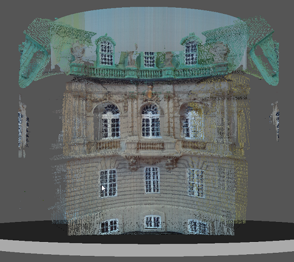
Here is two screenshot from last scan. I just can't get my arms down ![]()
![]()
I know there is still alot of work to do, like remove noise, change settings etc. BUT ![]() IT WORKS perfect !!!!!
IT WORKS perfect !!!!!
Btw. Those new babies i just bought, they wasn't that much improvement imo. The default pair, worked just as good.
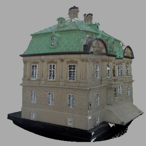
Well here is screenshot, and there is no hill below ![]()
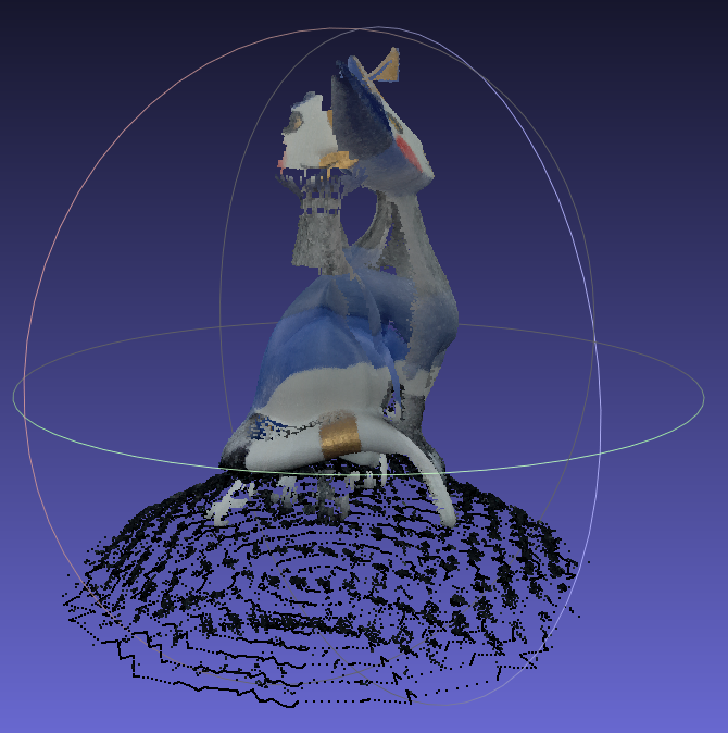
Here the cat earlier, now its down from its hilltop:
There is still alot of "errors" in it, just removed the worst noise, but now i will start to find optimal
light/settings to get the best result.
But its better than i hoped for ![]()
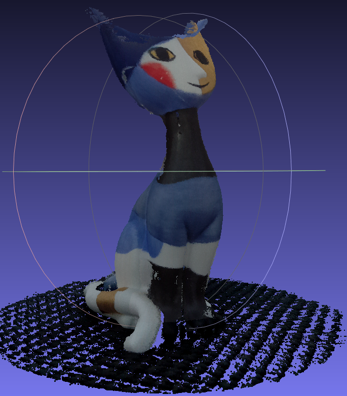
Reversed lasers.... Know we all know when we see that kind of deformation.
Nice job with the scans.
Good job! You will enjoy your Atlas3D very much.
I have played with the settings of Noise Removal, Image Threshold Mode and Laser Threshold, which has helped with noise and geometry detection.
SoliForum - 3D Printing Community → ATLAS 3D & FreeLSS → deformation test
Powered by PunBB, supported by Informer Technologies, Inc.