Topic: Kit for Calibrating X and Y with a Dial Gauge
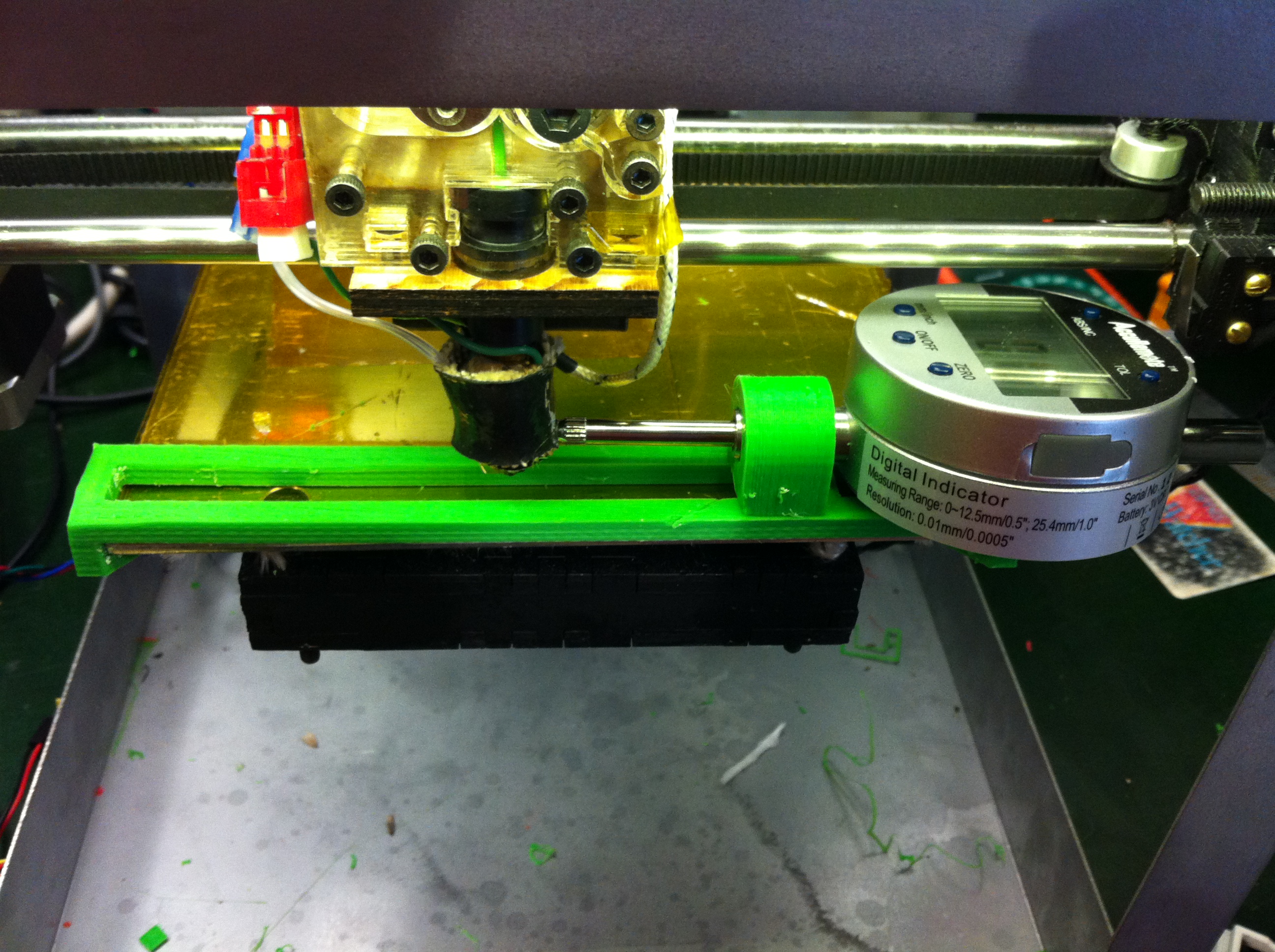
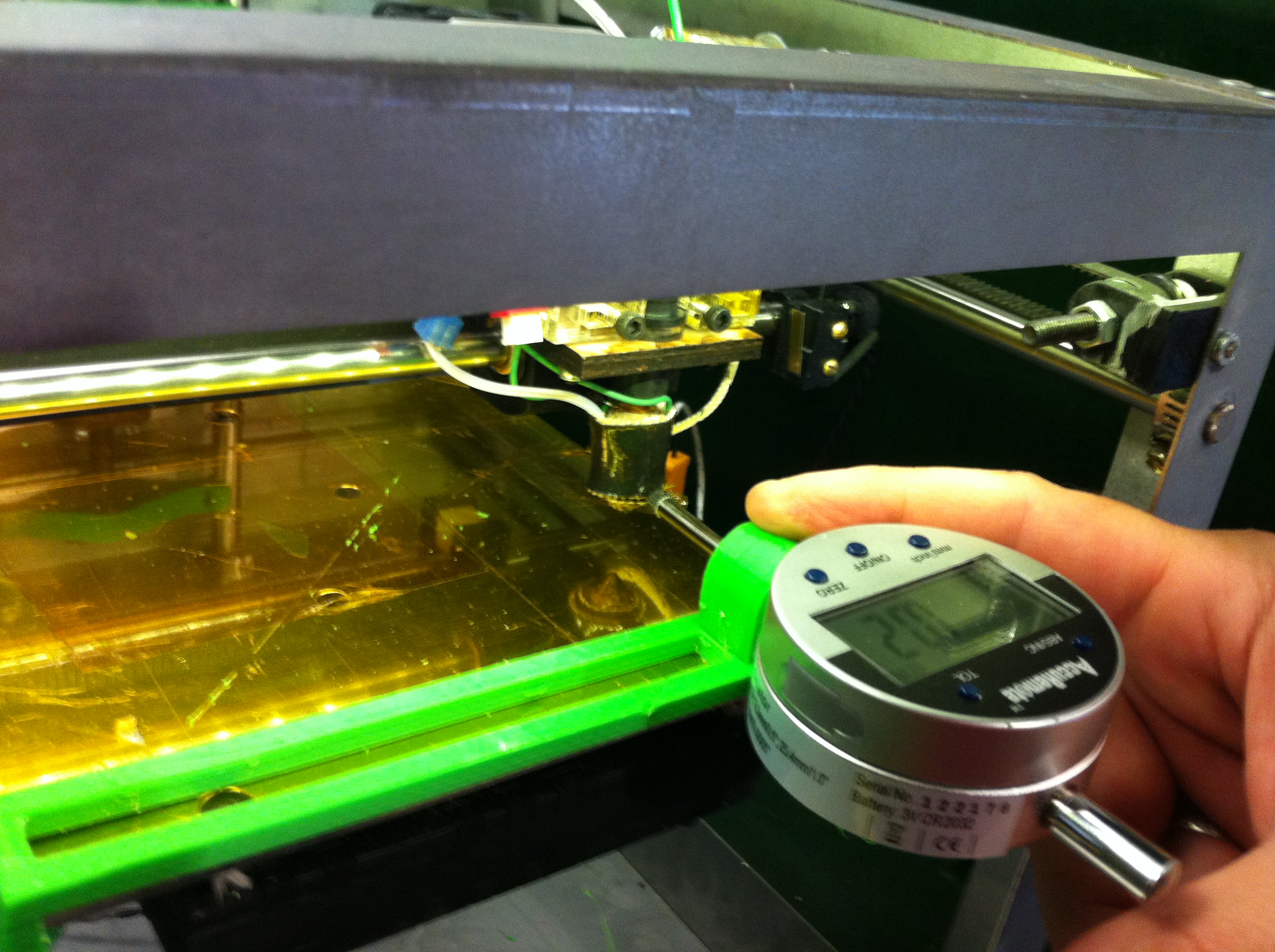
This is a kind of a rail that slides on to the printbed, and a piece that fits into the rail with a hole for the dial gauge.
For X, push the gauge holder back against the stop and hold it steady. Give the nozzle a head start and move it toward the plunger until it barely moves it. Zero the gauge and then move the nozzle against the plunger 10 or 20mm. Record the actual movement vs the commanded movement.
For Y, turn the gauge 90 and set it in the rail, holding it down with your finger while doing the same test in the Y direction.
Print both of the pieces with support. Support is needed under the triangle parts and under the tab of the gauge holder. In Advanced settings in Slic3r you can set a separate extrusion width for support material. I used .7 which means 70% of the width used for the rest of the print, and made the supports thin enough to pull off.