Removing the lead screw takes about 15 minutes... most of that for dis-assembly. I had to use 3 jam nuts (5/16-18's) to get it off the motor. Screw two to the bottom, grab a couple of pliers (It took me 2 as I had to hold the screw with one and the nuts with the other), then rotate to apply pressure to the motor. After a couple of turns, both nuts were spinning freely, but the shaft was still not free. I added another nut and did some more turning and the shaft literally popped off. Then I just had to superglue the new screw onto the motor shaft and wait. Re-assembly took another 5 minutes. Total time was about 30 minutes to remove, replace, re-assemble.
I noticed immediate improvement in the quality of the prints. Minimal banding at best and I managed to reduce that even further by slowing down the perimeters.
As for 3, if you can afford it, sure, but you should only need the one, unless you were sent another bent one which shouldn't be happening. If you really want to test, get one new screw and a coupling. Test the old screw with the coupling, then the new screw. Would be a full afternoons work, but you'd get your answer.
Edit:
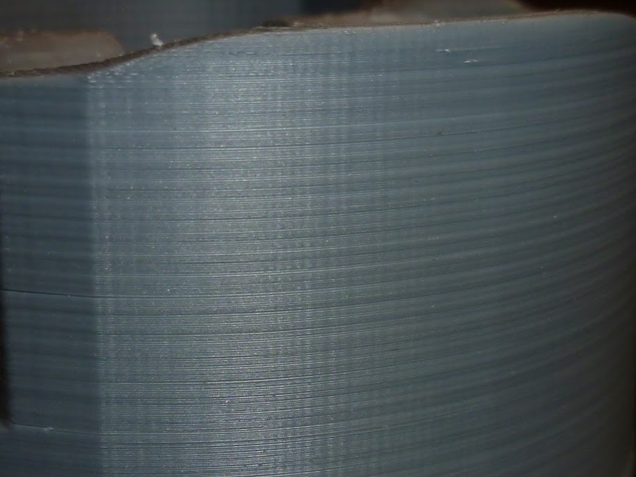
Adding a pic of before/after replacement. Same STL file used for both prints, .3 mm layer height.
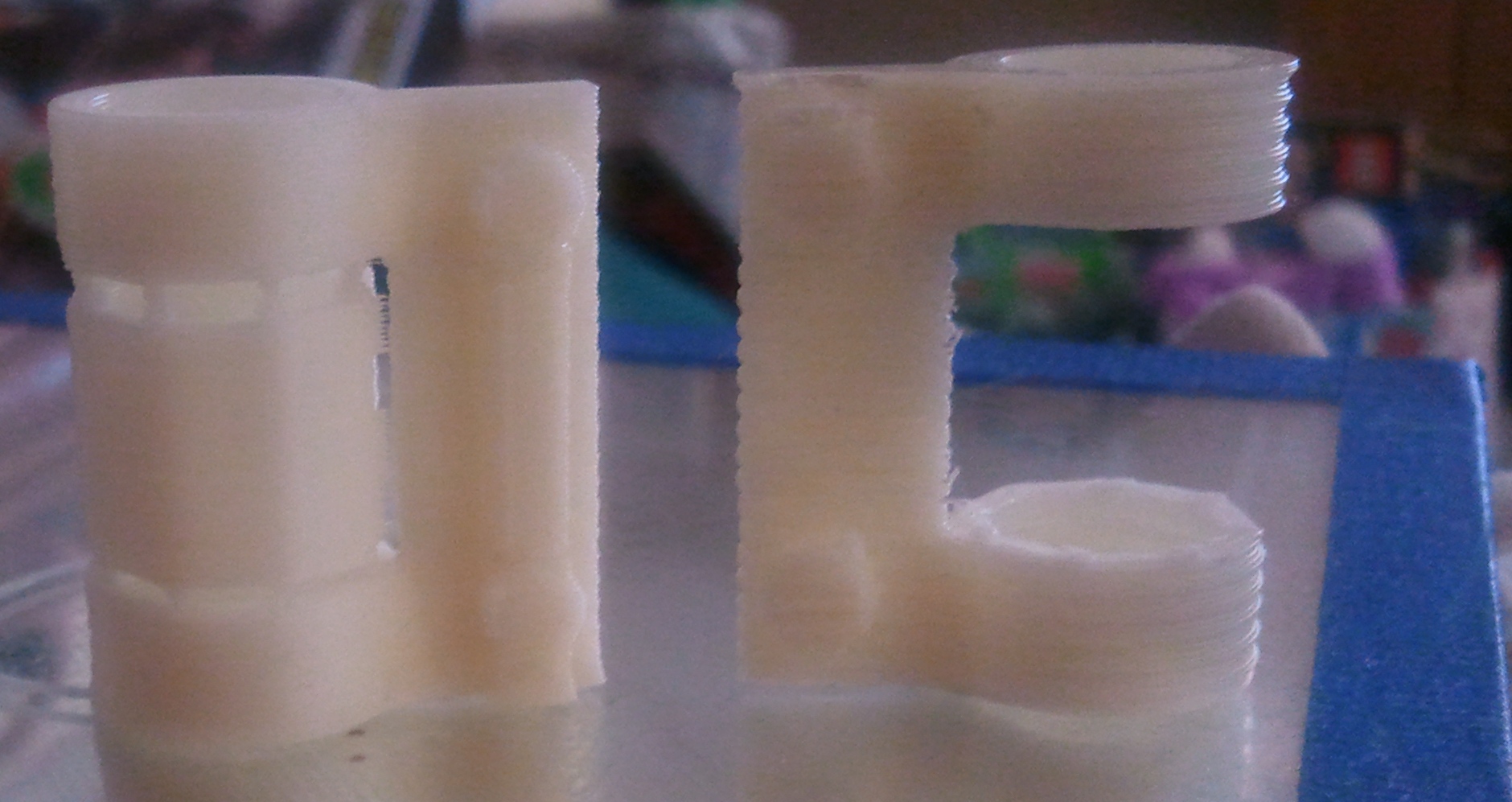
As you can see, the left one shows considerably less banding than the one on the right. This is the degree of bend that was in the lead screw that I replaced. I get some pretty respectable prints now and I'm working on getting the .1 mm layer height configs to work.