Topic: Double Endstop Idea
Does anyone want to try this?
I am too lazy...
You are not logged in. Please login or register.
SoliForum - 3D Printing Community → Solidoodle Discussion → Double Endstop Idea
Does anyone want to try this?
I am too lazy...
Oh and if it works, can you guys do it for all 3 axisseses? ![]()
Edit:...i keep staring at the GIF thinking its gonna print me something.
Good idea... mechanically.... the only thing I would change is get rid of the sliding rod support... move it to the side of the endstop switch and lengthen and put a z bend in that end of the rod so the bend pushes the switch, then changing the software shouldn't be too hard- if I only had more free time but work just picked up and now I can barely keep up with printing.
nice idea
except that it wont ever know if its hitting the + limit or the - limit... so it doesn't know if it needs to reverse or forward to come off the end stop. Net result is at best it can emergency stop the printer... then you;d need to re-home everything again as it would loose its print co-ordinates...
So mechanically sound... but not so sound as far as adding additional 'end stops'....
Just buy a RAMPS board and then you can have a proper +/- end stop pair... would be more reliable and functional than the above ![]()
nice idea
except that it wont ever know if its hitting the + limit or the - limit... so it doesn't know if it needs to reverse or forward to come off the end stop. Net result is at best it can emergency stop the printer... then you;d need to re-home everything again as it would loose its print co-ordinates...
So mechanically sound... but not so sound as far as adding additional 'end stops'....
Just buy a RAMPS board and then you can have a proper +/- end stop pair... would be more reliable and functional than the above
This is true with the software in it's current iteration, that's why you would have to add direction registers... there are some shortcuts that would work also but no failsafes if you lose steps.
Could you just wire the endstops together? You would have to change the code somehow so it knows which endstop it hit based on the direction it was going. If it registered an X endstop hit while the printer was moving left, then it can guess it was the left (-X) endstop. An X endstop hit while it was moving right would have been the +X endstop.
^ brilliant ^
can't believe I didn't think of that [slaps forehead]
My original idea was just to make everything stop and maybe home itself if either side reached it's limit. I was tired of the motors banging against the sides that dont have endstops and making that terrible noise (due to my own click-happy fingers of course). I would think that if an endstop gets hit while printing, the print should be aborted anyway because it means the model is too big to fit and should be resized, no?
Howcome you guys want it to continue printing? (Im not asking sarcastically im just curious.) And if it did continue to print, how would it print since it's already reached its linear limit? Would it ignore the remaining distance and just make a flat wall?
Just buy a RAMPS board and then you can have a proper +/- end stop pair... would be more reliable and functional than the above
Mybe if I understood how electronics work... To me everything with electronics works off of magic and pixie dust.
Isnt it just easier to set the software limit then. There is a firmware setting that limits the movement to a max value. If you home it will only allow 150 or 200 mm movement depending on what value you set.
This entirely solved my over eager manual inputs and have not ever had the carriages crash since... I do have a RAMPS onboard, but due to the above setting never bothered with the second set of end stops.
Seems an easier approach too
Could you just wire the endstops together? You would have to change the code somehow so it knows which endstop it hit based on the direction it was going. If it registered an X endstop hit while the printer was moving left, then it can guess it was the left (-X) endstop. An X endstop hit while it was moving right would have been the +X endstop.
How can I do?
Also how would you wire it? From the way I thought how things work is that the endstops make a closed circuit when they are hit and it makes the motors stop. And, of you wired 2 together using the same terminals, they will never make a closed circuit because one side will always be open... Like i said, i have no clue how things really work just what i though happens and my reason for coming up with the original idea.
I would much rather mount another endstop on the otherside if all it meant was soldering 2 wires together. (And you guys do the pixie stuff)
I'll tell you where to set the software limit later on, but you don't need a second switch in the scenario I explained just above. The firmware just doesn't allow more movement than you specify. You just need to home the printer as soon as you connect to it which is a habit you probably have picked up already.
Since doing this like I said I've never managed to crash the carriages
Isnt it just easier to set the software limit then. There is a firmware setting that limits the movement to a max value. If you home it will only allow 150 or 200 mm movement depending on what value you set.
This entirely solved my over eager manual inputs and have not ever had the carriages crash since... I do have a RAMPS onboard, but due to the above setting never bothered with the second set of end stops.
Seems an easier approach too
So, I could have gotten the same effect by cutting and pasting some text to the firmware?
:-(
I really should learn stuff...
In configuration.h ; change the following:
#define min_software_endstops false //{SD Patch} //If true, axis won't move to coordinates less than HOME_POS.
#define max_software_endstops false //{SD Patch} //If true, axis won't move to coordinates greater than the defined lengths below.
As you'll note, they are actually patched to false in the Solidoodle firmware. I personally switched max_software_endstops back to true and voila! problem solved.
Just make sure that the sizes in the following lines of Configuration.h from the above settings *is* set to the right size for your model.
Only time its possible to crash now is initially turning on the printer as the firmware will be at 0,0,0 co-ordinates until you home, but as I said, my habit as soon as I open RH is to hit the home button...
The software endstops do depend on a habit of homing. After a restart, and if you move it around with the motors off it will lose track of where it is. It can either allow a crash or stop halfway across because it thinks it is at the end. Hitting home all every time you finish doing something will help it work better. I suspect Repetier itself does some software endstop function on its on based on printer settings but I'm not sure.
Thanks guys for the great help. Glad I was too lazy to go through making that lever thing.
And yes, I always home before I print. Right after i click home, I prime the nozzle and click extrude a bunch of times then print. I know thats what the skirt is for but i guess i have a little OCD.
One thing though, i bought one of these these isp programmer thingies because my atmega 644p doesn't have a bootloader burned in apparently. Where do i plug it in on the sanguinololu? I see theres 6 pinouts next to the upper right screw but not sure and i don't want to fry anything. Tried google and youtube and found a bunch of tutorials using a breadboard and a bunch of other stuff i don't have, but nothing about using one of these programmer things.
The ICSP ports. Check the sanginololu schematics on the reprap wiki, but they are the top right group of 6 pins if you look at the card from the rear
http://reprap.org/wiki/File:Sanguinololu_1.3a.png
In this pic, they are the bottom-right group of 6:
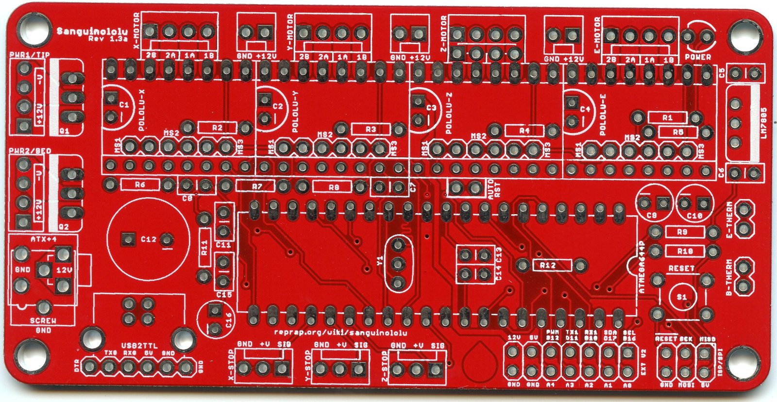
Don't worry about hooking up the +5V if you power it via USB when you are programming it. This is the only vague potential 'cause something to get fried'... Choose ONE way to power the Sang... USB, the Standard Mains, or via the Programmer and the 5V pin in the ICSP group.
You WILL however need the Gnd connection. Then from the programmer its a matter of hooking RST to Reset, MOSI to MISO, and MISO to MOSI (these are essentially 'in and out' or tx/rx.. but they aren't, so lets move on...) and SCK to the Clock pin on the programmer (often labelled CLK) .
Thats all you need..
Mybe if I understood how electronics work... To me everything with electronics works off of magic and pixie dust.
Everything electronics works off of magic puffs of smoke. This is proven by the fact that when the magic puff of smoke is released the electronics no longer function.
An oldie but a goodie.

This hasn't quite been mentioned but you can't use a single endstop switch for both for the simple reason of starting point.
When the printer comes on and the endstop switch is already activated which way do you move?
There is no last movement direction info, well unless you modify the firmware to store direction changes to the EEPROM every time but I doubt that would last long and it sure would slow down printing.
Nice idea to try and stop it crashing as an Estop, but then your printer gets stuck and needs manual intervention.
As Adrian said, software limits are the simple solution as long as you home all axis before printing (or playing about ![]() )
)
So, I'm probably doing something really wrong but I keep getting:
avrdude: warning: cannot set sck period. please check for usbasp firmware update.
avrdude: error: programm enable: target doesn't answer. 1
avrdude: initialization failed, rc=-1
Double check connections and try again, or use -F to override
this check.
I almost sure I'm connecting everything correctly but I really haven't a clue.
I tried in Windows and on the Mac using Arduino IDE 1.0.4 (on both OSes) and 0022 on the mac.
Been looking all over the net to aid me but I still get that error.
I tried doing -FUSBasp to override but then it tells me I didn't specify the device.
I didn't try to update the firmware of the USBasp because it seemed like a another huge task that I have no idea how to do.
I read somewhere that making it use a slow SCK with a jumper or something will help but again... no clue.
Anyone know where I can just buy a new ATmega1284P with bootloader burned in? It's becoming a big pain in my buns and I don't want to deal with it anymore... or is upgrading also a huge pain in the buns because of the firmware?
Thanks again solidoodle for not including the bootloader on my chip...
http://www.ebay.com/itm/ATmega-1284P-PU … 3381652c6e
I'm sure there is some others out there. Just search for atmega1284p marlin or reprap .
Re the loader, try swapping MISO/MOSI... and using the usbasp loader details
SoliForum - 3D Printing Community → Solidoodle Discussion → Double Endstop Idea
Powered by PunBB, supported by Informer Technologies, Inc.