1 (edited by caswal 2013-01-10 14:13:53)

Topic: Crazy Z Suspension Carriage Concept (To Reduce Banding)

This banding issue has been bothering me. I know that Solidoodle are working on a fix, but I love trying to solve problems. I am a programmer by trade, so problem solving is all I do tongue

My banding is very subtle, the Z-Nut fix has helped, but it still has some wobble. You can see my post talking about it here

So, I keep thinking to myself, there is quite a bit of play in the bed. The bushes against the Z rear rails have quite loose tolerances. So I setup a simple third rail guide rail, using the threads for the door hinges to hold some brackets. And designed an arm to screw to the bed:

https://lh6.googleusercontent.com/-cV-s1S72Wg8/UO7GOvGVMJI/AAAAAAAAA_E/m_DdZztYuBs/s1152/IMG_6671.JPG

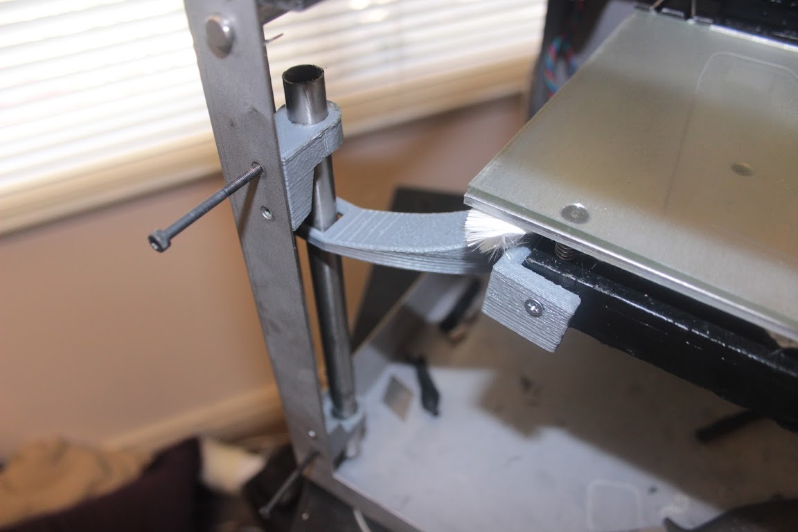
It has taken some of the slack out, but with my laser pointer wall test, was still getting about the same amount of wobble. As it can still wobble at the rear due to the lead screw. This third rail has not restricted the extruder movement, and with a modified bottom bracket design, will not limit the bed movement either.

So my next thought has been, how can I decouple the X/Y plane from the lead screw. Some people have been using a universal joint between the stepper motor and the lead screw, but that doesn't fix a lead screw with a slight bow/bend.

So I started to design myself this crazy contraption. It is designed to hang the bed off a couple of cables. So the lead screw can wobble the carriage, and the length of suspension wire should reduce the wobble seen by the bed. Here are some pictures of my concept:

https://lh5.googleusercontent.com/-Dwc5SBeJV1I/UO7JT_pvnGI/AAAAAAAABAI/BFHhleh_8Lk/s640/SD%2520New%2520Carriage%2520Front.jpghttps://lh4.googleusercontent.com/-mQLv7q04XCk/UO7JT5CaIvI/AAAAAAAABAE/pbXMIhw0KGw/s640/SD%2520New%2520Carriage%2520High.jpghttps://lh3.googleusercontent.com/-U20LDlA8x4k/UO7JTw6R5uI/AAAAAAAABAA/T6x80OPhLmE/s640/SD%2520New%2520Carriage%2520Low.jpg

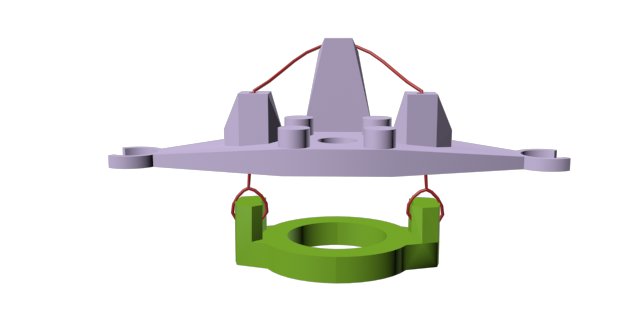
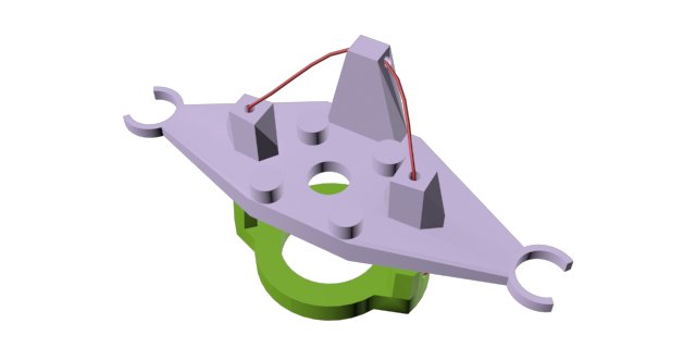
The 4 pegs on top, are to make use of the 2 part Z Axis fix print.

The bottom eyelet piece, I am going to redesign to print on its side or at a 45 degree angle, to make better use of the grain of the print. To make it stronger along the points of stress.

Thoughts, opinions? Should I give it a go, am I being an idiot? It is all designed to allow me to go back to the standard setup of it doesn't work or help.

Lead Programmer & Co-Owner of Camshaft Software - Creators of Automation - The Car Company Tycoon Game

2

Re: Crazy Z Suspension Carriage Concept (To Reduce Banding)

Does your banding wrap around the printed pieces like threading on the leadscrew or is it layered banding?  I think another interesting test with your laser would be to secure it to the bed and point it straight up and see if the movement is in a circle and how it correlates to the amount of movement in the z direction. I still think the best solution is to get a better leadscrew, but this looks like an interesting upgrade for super hi res printing. How would the bed be secure and stable with this design?

3

Re: Crazy Z Suspension Carriage Concept (To Reduce Banding)

Couple of thoughts:
1) Good idea to isolate the z motion from x and Y - this looks like a great idea to try.
2) You need a bearing surface against the rails for the Z motion part (the top part).  It looks like you have clip on mounts which are there to keep the top item from rotating.  But ANY rotation of that item would show up as Z axis backlash because the nut would rotate with the rod, instead of threading and giving you z axis motion.  Those clip mounts have to be fairly precision so you don't get any rotation.
3) Does the bed move freely enough that gravity will be able to move it down at the proper rates?  The Z axis will no longer push the bed down, it will only allow the bed to drop - so the bed needs to do that on it's own.
4) My clip I use for my anti-backlash thing (holds extra nut and spring, and has arms extending to the rails - looks almost like your top part) actually wobbles, I wonder if your top item (that clips on the rails) is going to wobble or rock left and right.  If it does, I would expect that will get translated through the cable system to the bed and result in uneven Z lift (even if it does not push X and Y).  This would have the effect of making your Z steps calibration change as the part wobbles.

4

Re: Crazy Z Suspension Carriage Concept (To Reduce Banding)

Just as reference, there is also discussion on the Google group about this same sort of thing.
https://groups.google.com/d/topic/solid … discussion
Kendall over there has some good ideas on isolating the lift from X and Y movement.

5

Re: Crazy Z Suspension Carriage Concept (To Reduce Banding)

rickk wrote:

Couple of thoughts:
1) Good idea to isolate the z motion from x and Y - this looks like a great idea to try.
2) You need a bearing surface against the rails for the Z motion part (the top part).  It looks like you have clip on mounts which are there to keep the top item from rotating.  But ANY rotation of that item would show up as Z axis backlash because the nut would rotate with the rod, instead of threading and giving you z axis motion.  Those clip mounts have to be fairly precision so you don't get any rotation.
3) Does the bed move freely enough that gravity will be able to move it down at the proper rates?  The Z axis will no longer push the bed down, it will only allow the bed to drop - so the bed needs to do that on it's own.
4) My clip I use for my anti-backlash thing (holds extra nut and spring, and has arms extending to the rails - looks almost like your top part) actually wobbles, I wonder if your top item (that clips on the rails) is going to wobble or rock left and right.  If it does, I would expect that will get translated through the cable system to the bed and result in uneven Z lift (even if it does not push X and Y).  This would have the effect of making your Z steps calibration change as the part wobbles.

There should be zero play with the clips, They are currently about 0.4mm to small for the bar, and relying on the give in the abs to clip them on.

In reply to point 3 I honestly don't know, and in fact is a little bit of an oversight on my part. I might put this whole carriage concept on hold, the bed doesn't have all that much weight, with the alu bed, and plywood base. So I don't think it would reliably drop, but no worries, it was a fun modelling project and practice.

I am seeing if I can assembly together an upgrade kit. Comprised of a new lead screw, flex joint for the stepper to screw, and a ball bearing fitting for the top of the frame, connected to the case. Would people be interested in this?

Lead Programmer & Co-Owner of Camshaft Software - Creators of Automation - The Car Company Tycoon Game