Topic: Solderless Main Powerswitch Mod
Perhaps my Solidoodle is strange, or other people put up with it, but it was really bugging me how the SD always runs the extruder fan and LEDs. Where my Solidoodle is situated, it plugs into a plug board with the computer, projector etc. So I just have the SD's power brick on the table and pull the power coord to stop the fan/LED's. So I decided I would make a proper power switch, print a enclosure for it, and document the whole thing.
Now I did do a little soldering, I like to have the tips of the wires tinned for the terminal block, and I ran out of one connector, so cut and soldered a spare I had off some old car wiring I had, but you don't have to do this.
Parts List:
High Current DPDT Switch, like this one: http://www.jaycar.com.au/productView.asp?ID=SK0983, (although as it is 12v it doesn't light up).
6x Spade connectors, female
2x Spare connectors, male like these: http://www.jaycar.com.au/productView.asp?ID=PT4630
Large Diameter shrink wrap (You might not need this if you are using insulated Spade connectors).
Large gauge wire, preferably at least 2 colours (blue/black or red/black), 15 amp
Tools:
Wire Stripper
Crimper
My favourite is this tool, does both, it is amazing! http://www.jaycar.com.au/productView.asp?ID=TH1827
The reason the switch has to be a DPDT is that due to the bug in the Sanguino board design, if you just cut the live wire, the 5v feed to the LED's and Fan's sources 5v from the USB, but seems to ground through the power supply. A DPDT is 2 switches in one, so it cuts both the live and ground feeds.
Step 1:
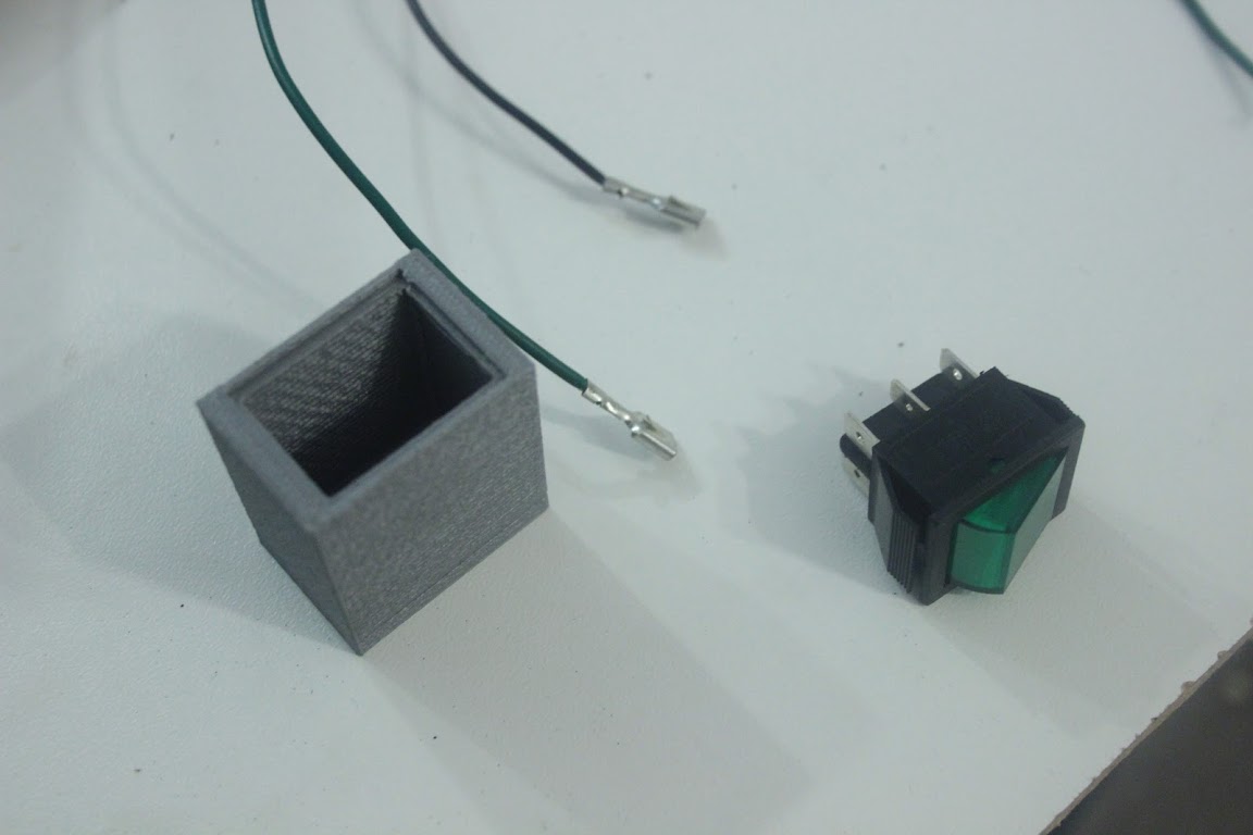
Print the housing for the switch, see below for the basic STL, it has no mount points as I am going to be getting some perspex to build some covers in the near future, so not sure how this switch is going to end up.
Step 2:
Unplug the power supply from the mains, and USB cable from your SD.
Step 3:
Cut 4 pieces of wire (2 of each colour) about 30cm long. Strip both ends to have about 4mm of exposed wire, twist the exposed wire to stop them from readily splaying apart, and crimp on 4 female spade connectors. See image below:
Step 4:
Connect the 4 coloured wires in the following way:
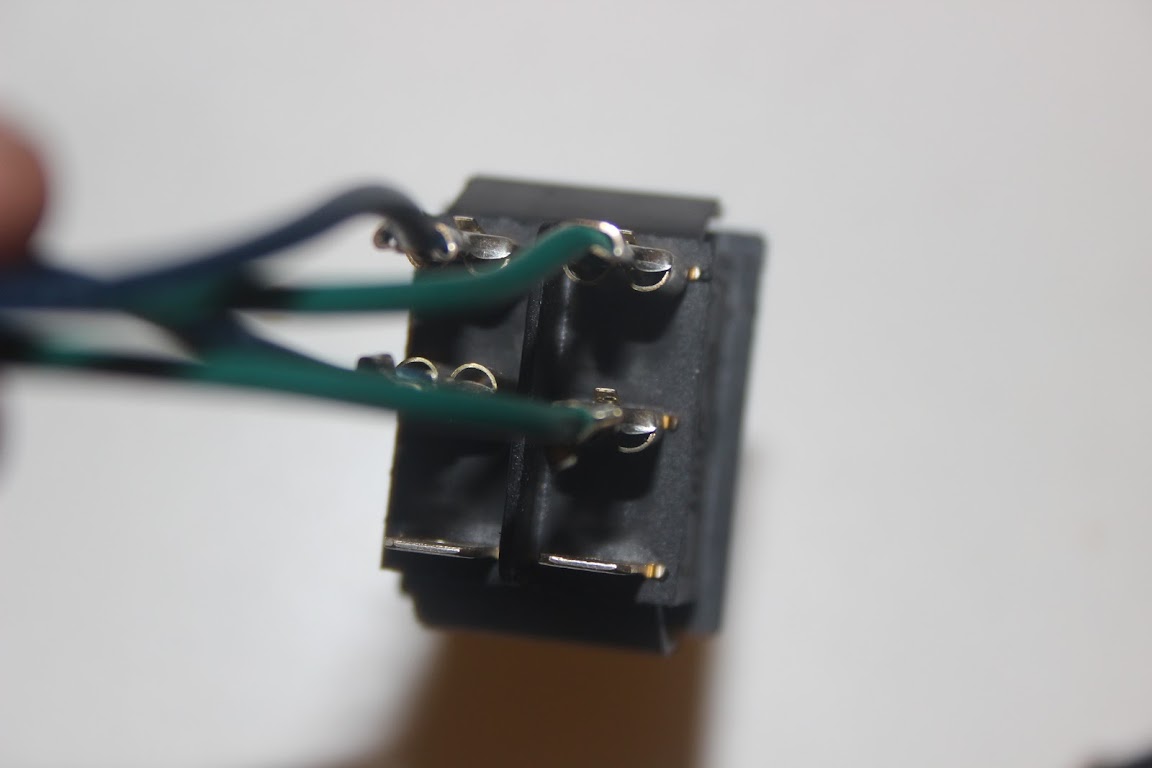
The 3 pins on each side are the separate switches. The middle pin is common. As you rock the switch from one side to the other. The switch is closed to either both pins on top, or both pins at the bottom.
Step 5:
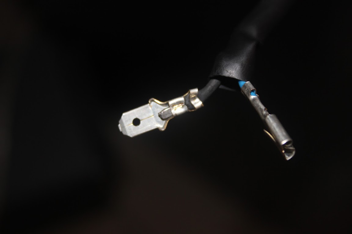
Unscrew the power wires from the terminal block on the Sanguino. To help yourself in the future, on the power supply crimp a male connector on the ground (Black) and a female connector onto the live (blue). From the two top leads of the switch, crimp a female on the black wire (Opposite to power supply ground) and a male connector onto your live switch wire (green in my case).
The power supply end should look something like this:
Optional Step 6:
I tinned the uncrimped ends of my 2 wires from the switch, if your wire is copper it the exposed ends will oxidize, also they are a bit more of a pain to feed into the terminal block without splaying and causing a possible short.
Step 7:
Feed the wires into the switch enclosure, out of the hole at the bottom, push the switch into the house until it is flush with the top:

Step 8:
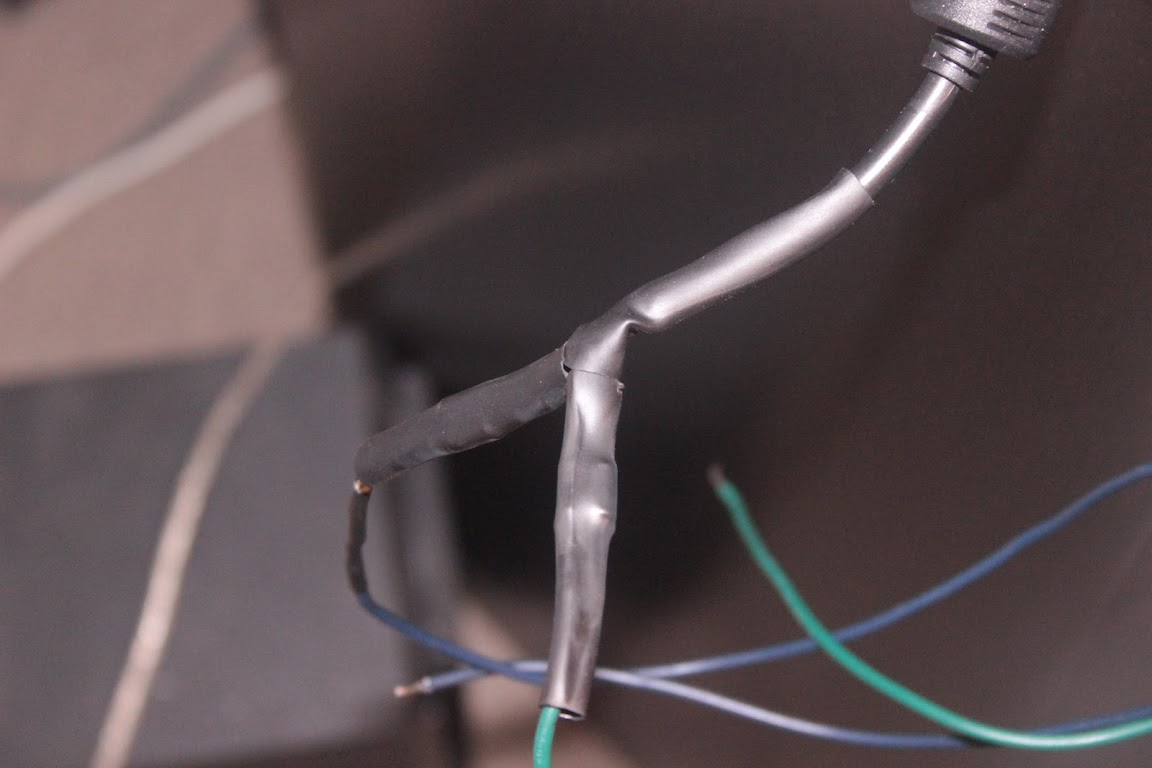
Cut some heat shrink about 4-5cm long and put them over the switch wires with the spare connectors. Now connect these to the power supply. Sleeve the heatshrink over the terminals and use a lighter/matches to shrink it:
Step 9:
Connect the live and ground wires to the Sanguino again, if not tinned make sure the wires do not splay and fully pressed into the terminal block. If you kept the exposed wire short (about 4mm), then you can press them in until the insulation is flush with the terminal block. The ground (black) is at the top of the terminal block.
Step 10:
All done:
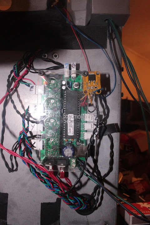
Picture includes the Freetronics N-Drive that I use to control the G-Code Fan. Switch temporarily tapped at the top of the picture.