1

Topic: Another filament extruder design and build with machining!

Hello, I have a 3D printer coming from Kickstarter, so while waiting months for that to show up I have decided to pass the time designing another Lyman based filament extruder.  Why?

First, I am a mechanical engineer and love the design process. 
Second, I have a hard time buying stuff that I can waste more money and time on building myself.
Third, I have a basic machine shop and have not seen much in the way of filament extruders that have not been made with basic parts.
Forth, maybe it will work and maybe I will learn something new or make an improvement.

First of all, my hat off to those who have blazed this trail to make it easier for me.  Nothing like going down a well worn path.  I am definitely starting off from an easier point than many others have and realize it.  But I like putting my own twist on things, it is just part of being an engineer and part of the maker movement.

So the goals of my project are:
A filament extruder that looks nice. 
Produces tight tolerance filament consistently. (tolerance to be determined by what my prints need!)
Has multiple adjustments that will allow me to tune it for production or new blends.
Is modular to allow for future improvements.
Cost less than $1,000 for materials, but I am not really keeping track (Unless I go with a 3 phase 480v frequency drive motor setup!)
Could be used in a class room setting to teach high schoolers design concept and process control.
Have fun and get me away from my desk some!  I love making chips on the machines!

Equipment:  I have a nice mill and lathe, mig welders, plasma cutter, brake, roller, shear, press sand blaster and various hand tools available.  All the steel, brass, aluminum, nuts and bolts that I will ever need.

Ideas:
I want to play with AC motors to see if it helps with consistency at all.  Everyone else seems to have been using DC power, but I am really more comfortable with AC power. 

My barrel and heat chamber are designed right now to be a consistent smooth bore to fit the auger within about 0.01"  Not sure if that will help or hurt, but figured why not try it.  Most of the other ones seem to be made to be loose fitting.

Will look at water cooling the filament and possibly the tip of the nozzle also.  Current desing incorporates a screen, breaker plate and separate nozzle.  Haven't looked into venting to remove possible air bubbles yet.

Anyways, I will post a few pictures of what I finished up today.  had the Parkerizing tank out for some other parts, so I sand blasted the main body and parkerized it to a nice dark grey finish.  Offsets the brushed aluminum parts nicely I think!  Next up is to fabricate a motor mount for my Bodine 110 AC gear drive motor.  Had this laying around from about 8 years ago, figured I would try it first.

Anyways, hello and lets see how this journey goes!

Brian

2

Re: Another filament extruder design and build with machining!

befu wrote:

My barrel and heat chamber are designed right now to be a consistent smooth bore to fit the auger within about 0.01"  Not sure if that will help or hurt, but figured why not try it.  Most of the other ones seem to be made to be loose fitting.

Smooth bore could be a problem. Look at point 2 in this thread:

http://www.soliforum.com/topic/3935/pol … -tutorial/

Friction on the barrel wall matters. I'm not saying don't try it, but if you get low output rate that's why.

Typical home extruder design has "loose fitting" bore/screws because a 5/8" wood boring bit is a little smaller than 5/8", and the ID of a 1/2" NPT schedule 40 pipe is right at 5/8". Changing either of those is expensive. (custom screw, or custom machined pipe ID)

3 (edited by befu 2013-10-09 21:22:30)

Re: Another filament extruder design and build with machining!

Well, when I said smooth bore I guess I miss spoke.  I started with a piece of 1" OD structural tube and drilled it out.  I should have said a consistent bore.  I had originally thought about reaming the tube to size, but instead went with a 37/64 drill I think.  The surface finish is anything but smooth, but it is fairly close to the auger size. I used an Irwin brand 5/8" auger and when I cut the front few inches off, the main body diameter was 0.564".  The drill made the bore in the lower 0.570" diameter range. 

I did read your tech info first and that is what made me just drill it instead of ream it out.  Like I said, I am impressed with what you have offered the community as far as knowledge and product.  I appreciate the help.

Since I am machining all my pieces anyways, not using pipe already threaded isn't a hindrance.

Well, never mind on the pictures!  No links allowed yet.  And it looked nice!  Oh-well, time to go home and see family.  Couple days I will probably have enough post and then will upload the pictures.

Brian

4

Re: Another filament extruder design and build with machining!

I think the cutoff is either 5 or 10 posts.

The interior surface of the Filastruder's barrel is pretty rough - maybe something between 200 and 400 grit sandpaper.

Irwin augers do run small in my experience - but in your case it doesn't matter since you can match the barrel.

5

Re: Another filament extruder design and build with machining!

Sounds like a fun project but a waste of a perfectly good engineer. I think we need to find a spare engineer in here who can design a cheap plastic granulator so i can reuse all my failed prints and recycle them into Filistruder fuel :-)

6

Re: Another filament extruder design and build with machining!

brw_racing wrote:

Sounds like a fun project but a waste of a perfectly good engineer. I think we need to find a spare engineer in here who can design a cheap plastic granulator so i can reuse all my failed prints and recycle them into Filistruder fuel :-)

Huh, never seen those words used together in a sentence: "perfectly good engineer."

Actually, that is a project that is on the list to do.  A little nibbler.  We use several larger pieces of equipment at work for particle size reduction and I have designed and built a couple also.  There are several options to look at for recycling print material.  The main problem to that is I do not have an extruder yet, or a printer.  So the process of recycling is a few steps off.  But I know it will come!

Having an account at a local shop that has laser cutting and water jetting available helps also!

Brian

7

Re: Another filament extruder design and build with machining!

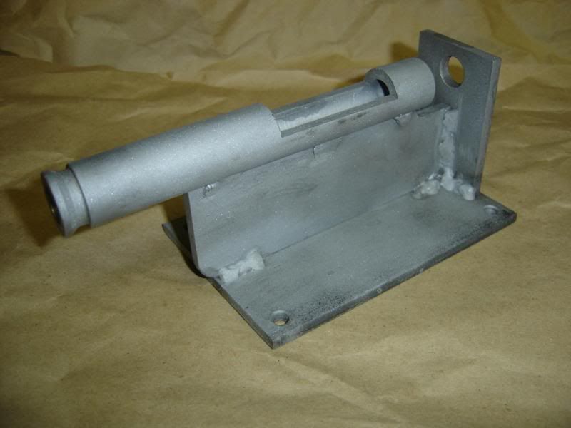
OK, try this again.  Gotten rusty on my welding!  Other side looks better but it is straight and solid.  This is just out of blasting before coating.

http://i63.photobucket.com/albums/h158/befunovo/DSC01484_zps710ddc9f.jpg

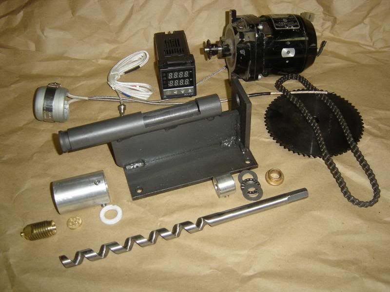
Here are the pieces I have so far.  A long way to go, but making progress.

http://i63.photobucket.com/albums/h158/befunovo/DSC01487_zps59607e42.jpg

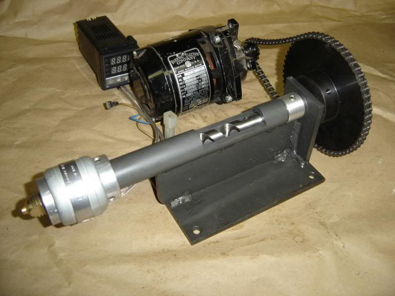
And here is what it looks like assembled so far:

http://i63.photobucket.com/albums/h158/befunovo/DSC01488_zps73ababc8.jpg

-The main body is all carbon steel with a phosphate coating for protection (Parkerizing)
-The auger is from an Irwin brand 5/8" auger bit, which I cut back to where it was a consistent diameter resulting in a 0.564 dia.
-The auger rides in a simple brass bushing.
-The auger is held in place by the aluminum collar that rides right behind the main barrel. 
-The thrust washer combo takes the pressure load from the auger against the back plate.  The back plate was welded on square with the aid of a fixture I made to make sure the auger spun true to the barrel bore.
-The sprocket goes on the backside and only transmits torque, it does not handle any side loads unless you try to push the auger forward, then it contacts the flange of the brass busing.
-everything else is the hot end of the extruder and needs more detail to be explained.  And it needs more machining and parts.

Oh, I also have a 24" x 16" vacuum former, so I may use that to make chain guards and such.

Brian

8

Re: Another filament extruder design and build with machining!

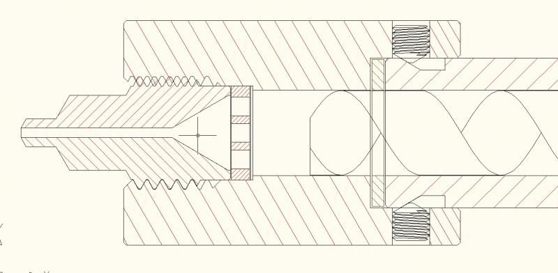
So here is a simple line drawing of the heat chamber end of the extruder.

http://i63.photobucket.com/albums/h158/befunovo/hotend_zps1f9d27d7.jpg

I wanted the heat chamber to be aluminum for the heat conductivity obviously.  The problem is heat transfer back up the extruder barrel.  Too much contact and the barrel will act like a heat sink pulling heat out of the chamber.  Warming the barrel might be good, kind of simulating multiple heat zones.  But I needed a way to control this.

So between the barrel and heat chamber I left a space for a small washer.  I can machine this out of an insolating material to limit heat flow or out of brass or aluminum to maximize heat flow.  The recessed groove on the barrel serves two purposes.  First it provides a tapered surface for the cone point set screws to contact to draw the chamber in against the flat of the barrel.  I have used this type of connection before in fire arm suppressors I have designed and built with good success (All ATF tax permits in hand, nothing illegal).  The other thing it does here is greatly limit the amount of barrel to heat chamber contact to lower the conduction area that is not controlled by the isolation washer on the front.

I am hoping to be able to control how much heat resides in the front of the barrel this way.  If too much heat does travel up the barrel towards the hopper, I can put a heat sink on the barrel just in front of the hopper.  This will give me a hot chamber, a heated barrel end and a cool barrel next to the hopper.  Will this add anything to the function?  No idea, but I can find out now!

The other end of the heat chamber I bored out to 0.625"  This gave me a shoulder on the inside to fit the screen and breaker plate against.  .625" dia also works for the 3/4-10 bottoming tap I cut the threads with also for the nozzle.  The circular screen will set in place first, then the breaker plate goes against that.  The nozzle then threads in and presses the whole assembly against the chamber step. 

The nozzle is made from a piece of 3/4 - 10 brass and is pretty basic with a taper input to the nozzle hole.  I left the end kind of long on this one, as I wanted to try running it before I machined it further.  I am wondering if I put some small fins on the end and leave it long if the nozzle tip will get cool enough to help solidify the filament as it is extruded.  Then maybe hit it with a water stream right out of the end.  All stuff to play with.  I know there will be a fine line between having the nozzle too cool that it jams up and hot enough.  If it doesn't work, I just make a new nozzle!

9

Re: Another filament extruder design and build with machining!

Now I have to admit I have been wondering about the consistent bore extruder verse the pipe flange that gives a larger pool at the end.  I will try it as is first, but something that Tim said about mixing in the coupler.  I have an extra auger so I can try modifying them.  I wonder about putting holes in the end of the auger to help create counter flows to increase folding and mixing in the heat chamber.  Or shorten the auger if need be, and put a mixer insert in the chamber after the auger.  Kind of a monolithic machined block to fold the molten material over on itself as it goes through.  I am picturing a short version of the mixer that you can put on the end of two part epoxies or urethanes so the parts mix as you use it.

I could also machine a heat chamber and recess bore it, so the chamber does have a larger diameter than the auger.  Or I could make the heat chamber out of two pieces, so it could be a recessed bore and have a mixing insert in it.  Looking at how the home brew extruders work, I do not think this would really add anything, but having the ability to make new parts and try it is helpful.

Oh-well, have plant manager stuff to do now, back to work.

Brian

10

Re: Another filament extruder design and build with machining!

I have played around with making a threaded brass barrel to thread into the nozzle opening to extend the land, kind of what you have done with the end of this one.  I wanted to see if I could cool the filament a little and have it come out a little more rigid.  I also have done that to provide something to screw a PTFE nozzle onto for the same reason.  I found that there is a very fine line between hot enough to extrude, and jamming.  It seems that the temperature right at the exit has the most effect of extrusion rate.  I don't know how the temp in the melt zone and the temp in the die relate to each other.  It might be a good idea to add a thermocouple and a little nichrome wrap to the end of the nozzle so you can directly control the temperature there

11

Re: Another filament extruder design and build with machining!

I think a big part of this is the difference in available force.

The melt pressure in a Filastruder is 100-150 psi. This works out to about a pound of force on a 1.75mm crossection.

On the other hand, most extruder motors apply around 6-10lbs of force to the same diameter filament. This helps them cope better with driving semi-melted polymer through the PTFE in a hotend.