Topic: Backlash, Hysterisis and Wobble; an exploration of the topic
With all the 'hacks' and quick fixes going around, I think people including myself are starting to get confused of what causes what and why certain things are done or work. Consider this me thinking aloud. ![]()
Firstly, it needs to be said that Backlash and Hysteresis are inter-related. If we venn diagrammed them, we could put backlash wholly inside the hysteresis circle.
Backlash is the specific term used within mechanical engineering of gears and drive trains to relate to the clearance between *mating interfaces*. In the context of the Z axis on a Solidoodle, this is referring to the clearance/tolerance between the threads in the nut and the threads on the screw. There is 'play', which in something with large tolerances, could allow you to wiggle and wobble the nut on a thread as the interface is so sloppy. This slop, in a precision environment, would be measured in 1000th's of an inch, if not 10,000 of an inch. In an off-the-shelf-parts printer, we can measure these tolerances in 100's and sometimes 10's of an inch. Backlash also exists in the X and Y axis, as the standard belts dont fit *precisely* into the groves on the pulleys - there is wiggle room present which is also decidedly non-linear.
Heres a diagram; 
That gap between the faces of the teeth ("backlash" as labelled in the diagram) has to get 'soaked up' when you change directions. If you kept rotating that top gear anti-clockwise, it would remain pressed against the face of the lower cogs and you'd get precise movements in that direction. However, when you *change direction*, the initial bit of moving the top cog is going to be wasted 'catching up' to the other cogs face.. during that time, the motor driving the top cog might think its moved 1mm, but the lower cog its 'driving' might only move .9mm's...
The concept of an anti-backlash system is to essentially preload the faces of the nut to the faces of the thread in one constant direction - hence the common use of a spring trapped between two nuts to force both nuts to mate opposite faces to the thread (the lower nut has its bottom faces forced agains the thread, the upper nut will have its top faces forced against the thread). The way threads are cut into nuts also means wedging two of them together (but not locking them against each other) can 'soak up' the clearance issues, as the start of threads on one nut wont align with the start of the threads on another. This is why wedging two nuts together on a bolt can stop either of them from turning on the bolt.
Hysteresis in the case of the Solidoodle is another term thats used to refer to the 'lag behind of a system to its input'. The context here is "Move Z+ 10mm then Move Z- 10mm" *should* result an object moving clearly up 10mm, then down 10mm to *exactly the same point*. As a result of backlash described above, what you see actually happen is the table move up 10mm's, then perhaps down only 9.8mm's. This could be referred to as ".2mm's hysteresis" is its the 'lag' between what was input, and what happened. However, as its a mechanical interface, it is much more common to have this referred to as 'backlash of .2mm's'. The more you change direction on the axis concerned, the more 'out of position' it will get. Whilst backlash is loosely a constant, it isn't necessarily, as different weights, velocities, etc can all influence if it remains a constant backlash or instead perhaps varies between .1mm or .2mm etc. This means that doing 4 moves for example (up/down/up/down) isn't going to necessarily get you back to your starting point exactly. This is also because obviously the distance between each thread face isn't perfectly the same.. given we are talking already in 10's and 100's of an inch, it should be obvious that a 'small' tolerance change on a thread of only 0.01mm can start having different effects. This is also impacted by Wobble, described below, as the elliptical movement causes the clearance distances within the nut to change.
Backlash therefore comes into play primarily as a result of when you start a print (as the table moves up to home, then starts moving down during the print. This initial change from up to down can result in the system believing its moved down .3mm's but in reality its only moved .2mm's). It also has a huge effect if you use 'Z-Lift', as the system is going through an Up/Down cycle, and thus trying to soak up clearances, on every layer. As noted earlier, this effect is also present in the belts + pulleys as the teeth on the belt dont precisely mesh into the teeth on the pulleys. And this is why when your belts are loose the backlash becomes worse, as a movement command can in fact be entirely soaked up slackening or tensioning the belt and not in axis movement.
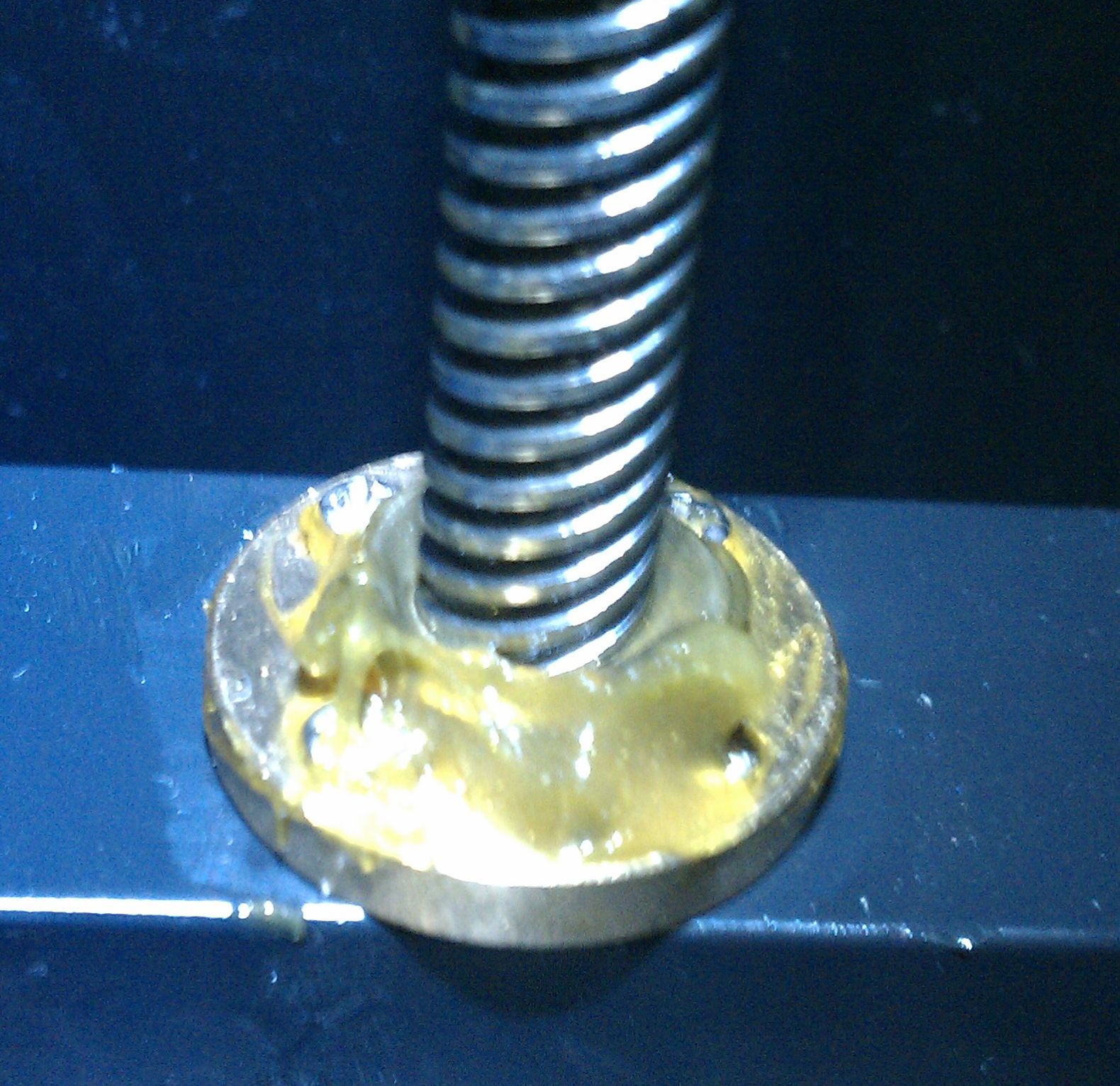
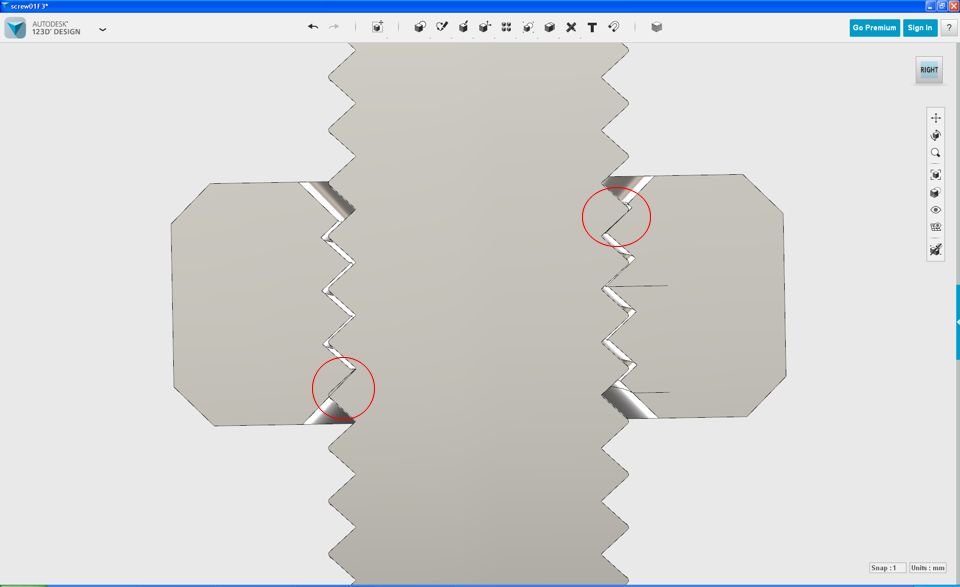
Wobble is pretty simple. Because the lead screw is mounted rigidly to the motor, it needs to be perfectly straight and square to the axis its trying to move. If its not, as the motor rotates, that offset will be converted into an eliptical motion instead of turning in a perfect circle. In big CNC world, as the axis is normally bolted to a huge/heavy table which refuses to yield to this movement, it results in breaking your motor or motor coupling (weakest point in the connection). This is what flex couplings are designed to fix - if you can't gurantee a perfectly square mating between motor and axis, you use a coupler with flex so that any movement can be soaked up in flexing the coupler and the lead screw/rod moves in a nice circle without busting your motor or mounts. This is true when you have a good solid supported connection on the lead screw like you'd see on a 'proper' CNC. However on the Solidoodle, as the top end of the Z-Axis is 'unsupported' and its only connection to *anything* is to the table via a tiny little nut, its free to 'flop about in the breeze' so to speak. Even a small 0.1mm offset from center can result in a much much greater 'wiggle' at the top of the screw clearly visible to the eye. Throw in even a 0.05mm bend in the rod, and it gets further amplified.
Adding better support to the axis, through a taller nut, multiple nuts, or supporting the end, would reduce the influence of this wobble. You do however, risk moving it to something else entirely - for example, making the lead screw rigid would mean that the forces would end up moving the motor itself, potentially causing fatigue issues with how its bolted to the sheet metal case (mine already moves a fair bit and its 'stock'.. making the screw rigid would see the motor having to absorb all that movement instead of half of it disappearing in movement of the screw...) . Solving the motor movement by securing it 'better' to the case would mean that the movement now gets soaked up in the motor shaft and bearing, leading to premature stepper motor death.
Wobble will also cause movements to not be linear, as some of the movement is again lost in a sidewards traverse of the lead screw instead of driving the table up or down. Going back to Backlash, Wobble clearly also influences the amount of backlash, and can even sometimes force the thread to move away from the face it was currently mated with inside the nut, meaning the next successive move doesn't actually move as much as it was supposed to. This causes the following layer to potentially be more 'squished' than the previous one and creating that tell-tale 'banding'.
The end result is the 'multiple' ways to 'fix' banding. For some people who have a negligible amount of backlash, reducing the wobble by use of either a flexible coupling, or taller nut making the interface between screw and table stronger, can resolve the issue. For others, the backlash is much greater, meaning that unless you eliminated the wobble all together, you'd never get linear motion anyway. This is where changing the rods out to a finer pitched rod can greatly improve things, not to mention that most people end up resorting to using a flexible coupling which also helps resolve the issue. Reducing just the backlash by having a proper anti-backlash nut etc, can greatly reduce the banding as it increases the prospect of linear movements of the table, but removing backlash without wobble will still leave you with potentially non-linear travel due to the side loading of the screw as it moves side-to-side instead of moving the table purely up and down.
And thus we have the result that the reason its 'not a simple fix' is because there is actually many inter-related issues going on at once. Fixing the wobble wont remove backlash, and fixing backlash wont remove wobble. And banding seems to be effected by both. How much so depends on the tolerance of your nut to your threads, how well centered your motor is to the table nut, and how well centered the lead screw is to the motor shaft. All of these things come together to determine if you need to 'fix' it with just a flex coupling, a taller table nut, an anti-backlash nut, or a new entire screw.
Simple huh ? ![]()
Keen for anyone thats still reading for input on what I hypothesized above ![]()