Re: [MOD] Rod replacement for ultra-precise 50 micron (0.050mm) Z layers!
you only need longer smooth rods, threaded rod, bed , belts .... ha, and a new chassis ![]()
You are not logged in. Please login or register.
SoliForum - 3D Printing Community → Hacks & Mods → [MOD] Rod replacement for ultra-precise 50 micron (0.050mm) Z layers!

you only need longer smooth rods, threaded rod, bed , belts .... ha, and a new chassis ![]()
But I hardwired the value in the Configuration.h of the firmware, since I wanted to update for a long time anyway.
Not intending to hijack this thread, but don't EEPROM settings override Configuration.h settings?
Back on topic - this is really an extremely useful thread and I really appreciate the contributions to it.
Regards,
Matt
Necromant wrote:But I hardwired the value in the Configuration.h of the firmware, since I wanted to update for a long time anyway.
Not intending to hijack this thread, but don't EEPROM settings override Configuration.h settings?
Back on topic - this is really an extremely useful thread and I really appreciate the contributions to it.
Regards,
Matt
Yep, I found that out when accidentally spotted that in the sources, already after two or so reflashes
Regular M5 nut, except two of them with an anti backlash holder.
Steps per mm was 4501.
Hm, strange. Where did that extra 501 step come from ?
Not sure what you mean. Original steps was 2268, new rod 4501.
The exact amount will change depending the pitch of the thread.
Not sure what you mean. Original steps was 2268, new rod 4501.
The exact amount will change depending the pitch of the thread.
200steps/rev times 16 microsteps/step times 0.8mm/rev (assumes M5-0.8 thread) yields 4000 steps/rev, not 4501
I can only assume my pitch is 0.7 in that case. Dial gauge confirms it is spot on.
I can only assume my pitch is 0.7 in that case. Dial gauge confirms it is spot on.
I have never in my entire life heard of a M5 x 0.7 thread. First time for everything!
Hm, I've just tripple checked mine with a dial gauge, looks like lawsy somehow got a different pitch (or my mind is playing tricks on me.)
A quick test reprint of a 18mm high with 4500 steps_per_mm setting gave me 19.9mm actual height. 4000 steps_per_mm gave me a 17.75 resulting height.
May be it's not metric? Like 5/16 is close to M8 but the thread pitch is not compatible with it. (Not a big expert on anything non-metric - just a wild guess)
M4 comes in .7, I wonder if someone didn't give you the wrong size?
I will double check the sizes of everything when I get home and post if it is different.
On another note my ballscrew has arrived from China and I'm machining the end to suit the coupling this afternoon.
Are there .stl files for the coupler and the bed attachment? I am eager to try this out my self!
Are there .stl files for the coupler and the bed attachment? I am eager to try this out my self!
Take the rod_mount.stl from the very first post. Print twice and you have the coupler.
Then, see my linked post for my custom bed nut holder. It is designed for 12x12x12mm custom machined nut, but there is the openscad design at my github, so you can adjust to your liking. The linked post also has instructions for custom nut machining.
Lawsy what is the ball screw for/ you mean a ball screw threaded rod?

One of these as a replacement for the threaded rod. I'm very happy with the M5 replacement however, so fitting this will be a low priority.
Just found some nice aluminum coupler avaliable dirt cheap in china: http://www.aliexpress.com/item/New-5-x- … 73121.html
That should give some better results, than ABS. Will post back,when it arrives (parcels to russia are damn slow)
i think this spyder type coupler is better because of the "no Z lag" of the mount
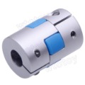
just to find one in 5mm-5mm.. cost more
Man that ball drive looks heavy duty and way over kill (load wise) will the servo drive it might need more holding torque or change your steppers out to keep them from overheating?
I assume it is super precise as well, how many steps will that give you?
lawsy wrote:Not sure what you mean. Original steps was 2268, new rod 4501.
The exact amount will change depending the pitch of the thread.
200steps/rev times 16 microsteps/step times 0.8mm/rev (assumes M5-0.8 thread) yields 4000 steps/rev, not 4501
This math threw me off I had to pull out excel, lol
1: the steps per rev is simple
200*16 = 3200 steps/rev (not in my case I have 1/32 steppers so I get double ![]()
Then this is fun math I made the 4501 mistake and got the same results right and wrong way ![]()
Lets get to the default 2268 steps per mm in marlin.
Your above math is confusing because you say times .8mm/rev. Because 3200 * .8 = 2560 steps ok. I was like wait that is only marginally better then the 5/16-18 so I backed into that
First _ did 18threadspi / 25.4 convert to mm = .708
ok so the stock sd is .708 so what is 3200 * .708 = 2267.7!!!! wow ok
So same math applied to .8 step = 2560 is this right? No right but what gives?
So what if I divided the 3200 by the pitch (thinking i had inverted wrong somewhere)
3200/.707 = 4515!!! ok so maybe that was mistake above. Still wrong right
SO I converted the 18threads per inch wrong! OK so what, here is the twist.
1/18 then = 0.055 inches per thread then convert to MM
0.055 x 25.4 = 1.411 pitch for the stock rod
so lets go back to stock conversion:
3200 / 1.411 = 2267.7
3200 * .708 = 2267.7!!!
both give exact same numbers even though .708 is wrong. Since if you applied this to another rod (steps x pitch you would be off)
So stock is:
3200 / 1.411 = 2267.7
And 5M-.8
3200 / .8 = 4000
But on my sure stepper I have
6400 / 1.411 = 4535
for upgrade
6400 / .8 = 8000!!!!!
I am a dork sorry for the rant
Since on the topic:
The X and Y are driven by the same 6MM bore pulley and a pitch diameter 11.5mm (outside path)
So 3200 steps in the servo
Pi*D = distance of pulley
11.5*3.14 = 36.36mm
3200 steps / 36.36 = 88steps/mm
This math threw me off I had to pull out excel, lol
Yeah, I did the math right but typed it wrong.
[200 steps/rev]*[16]/[.8mm/rev]=4000 steps/mm.
Dimensional analysis. ![]()
I figured that but the 2267.7 number thing surprised me pretty cool.
I will double check the sizes of everything when I get home and post if it is different.
On another note my ballscrew has arrived from China and I'm machining the end to suit the coupling this afternoon.
I know this is an old post but any updates on it?
I also think about using ballscrew for x and y and would love some feedback if you did it.
thanks
lawsy wrote:I will double check the sizes of everything when I get home and post if it is different.
On another note my ballscrew has arrived from China and I'm machining the end to suit the coupling this afternoon.
I know this is an old post but any updates on it?
I also think about using ballscrew for x and y and would love some feedback if you did it.
thanks
I ordered a ballscrew from aliexpress, excellent quality (for my use at least) and all my problems with the z-axis went away. Also a lot faster to move the z axis now. Recommended ![]()
http://www.soliforum.com/topic/10012/sd … installed/
SoliForum - 3D Printing Community → Hacks & Mods → [MOD] Rod replacement for ultra-precise 50 micron (0.050mm) Z layers!
Powered by PunBB, supported by Informer Technologies, Inc.