Topic: Looking for Solidoodle 3 aluminum bed support
If anyone is parting out an SD3, I am looking to upgrade my "wooden" bed support frame for the later aluminum part.... looks like this....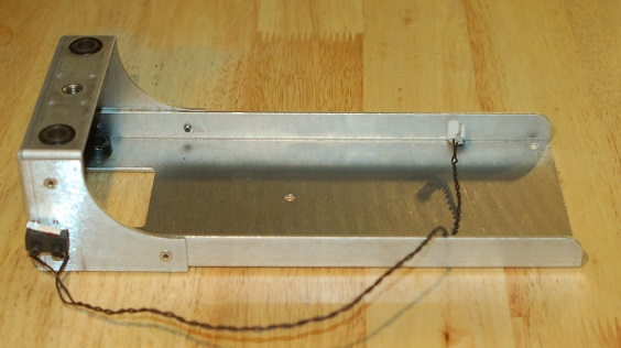
You are not logged in. Please login or register.
SoliForum - 3D Printing Community → Buy/Sell/Trade → Looking for Solidoodle 3 aluminum bed support
If anyone is parting out an SD3, I am looking to upgrade my "wooden" bed support frame for the later aluminum part.... looks like this....

Can I ask why? I have both styles and my opinion is the wood is more stable.
My wooden one has visible cracks in the black paint, which suggests that over time it may have sagged or subjected to stress.
As an engineer, I find it hard to believe that an aluminum structural support which appears to be 5-6mm in thickness would be less stable and have less structural integrity than wood which is prone to humidity changes and warpage due to stress. The solidoodle designers must have felt that going to the aluminum version was an improvement right?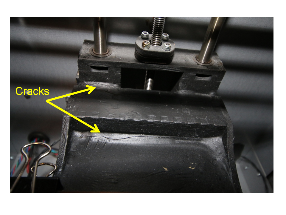
The humidity issue I would agree with. As for Solidoodle having engineers at all is fairly laughable. But I am clearly no expert on the issue. I was simply offering my observation is all. As for the cracks you pictured. Almost looks as though maybe,,, perhaps the glue was laid on too thick and cracked during the curing process.
It would be nice if some of our peers would jump in with other opinions.
Sorry, I'm no help. I didn't even know they made those out of wood.
-Kevin
Sorry, I'm no help. I didn't even know they made those out of wood.
-Kevin
In the early days wood was the only way printers where made. If you look at my avatar on here it is the original Cupcake by Makerbot and everything except electronics, rods, belts, and bearings are wood.
Geetech and others still use wood or particle wood. but Im with Knowack the early SD2 used wood but when SD3 replaced the SD2 they were already using Aluminum in the SD2 as I have both wood & aluminum for SD2 and I must say the Wood has held up surprisingly as rough as I have been on it. is this really an SD3 8x8 inch build plate size? thats lots longer leverage than the SD2 6x6 maybe thats why they went Aluminum
My wooden one has visible cracks in the black paint, which suggests that over time it may have sagged or subjected to stress.
As an engineer, I find it hard to believe that an aluminum structural support which appears to be 5-6mm in thickness would be less stable and have less structural integrity than wood which is prone to humidity changes and warpage due to stress. The solidoodle designers must have felt that going to the aluminum version was an improvement right?
as an SD4 owner (several in fact) I can verify that the aluminum bed support is NOT 5-6mm thick.. LOL
it is actually only 2.4mm thick, so, eh, make of that what you will.
also, the rivets that hold the structure together tend to wear and the whole thing will start to wobble a bit.
I have drilled out a few of them and replaced them with 3mm bolts/nylock nuts to keep things together better.
if you do go forward with the swap, I would highly recommend drilling out all the rivets and replacing them with screws/nuts before you install it.
save yourself the headaches of having to try to do it later. ![]()

OP- If you REALLY want an aluminum platform for an SD3, I will sell you mine. PM me if interested and we can hash out your options.
OP- If you REALLY want an aluminum platform for an SD3, I will sell you mine. PM me if interested and we can hash out your options.
Sent a PM.....

if you do go forward with the swap, I would highly recommend drilling out all the rivets and replacing them with screws/nuts before you install it.
save yourself the headaches of having to try to do it later.
The other option would be to install some real solid rivets . A whole lot better than pop rivets . IMHO what should have been used at the factory but. as we know 3d printers are often not built to aerospace specifications.
think the SD2 Aluminum bed should also have rivets replaced? I havnt used mine yet so easy done. maybe Stainless Steel if it plays OK with Aluminum
if using rivets use aluminum. nuts and bolts stainless is fine but more expensive to purchase. any steel aluminum connection will corode . but only in damp environments usually 3d printers are kept clean and dry.

you are talking about the humidity. at this time in the humidity in the room my printer is in is 52%
I have more problems with filament than corrosion. ( I live in north west FL. about 15 miles from the beach.
dale
Ok, so looks like no-one is willing to part with an aluminum SD3 bed support, so I am planning on building one out of 3mm carbon fibre. I have a Solidworks model I made but would like a fully dimensioned sketch of the hole locations if anyone has had theirs apart and dimensioned it.....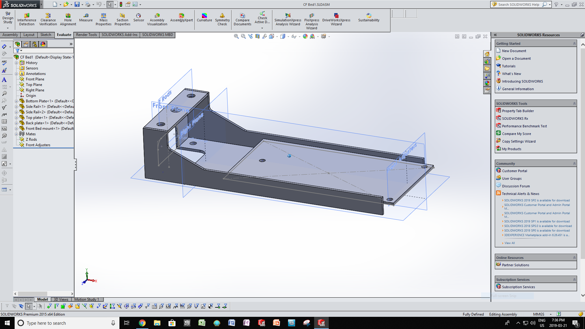
the holes would need to match the layout on your bed.
they are centered side to side - if that helps any.
Umm..... Yes, I have done my best to measure the key mounting locations with a digital caliper. However, if someone had their bed support out for some reason and happened to accurately dimension it, it would be nice to get a double check.... Having said that I am confident enough that my dimensions are accurate enough to get a quote from a machine shop to have the pieces NC cut from CF sheet.....
The CF bed support project is not a firm "GO", it will depend on the machining cost mostly....
The wooden one is not working badly, it just seems to me to be a bit 18th century....
In the meantime, I have some "fresh" ABS and the test prints are coming off flat and quite accurate. I have a E3D-V6 full metal with bowden ready to assemble and will be installing that shortly. I will be printing off the Lawsy carriages. (anyone have a Slic3R profile for that to reccommend?)
Next upgrades: MK7 extruder - on order, then a 5mm alum bed with Calidum heater....
Then will see how the printing has improved and go from there.
as long as the bed screw holes are within a mm or 2 they should be fine. The threaded rod & smooth rod holes will be more important.
for printing the carriages, you want high infill for strength.. no less than 75%, most will say 100% - with a minimum of 3 perimeters/shells
also, due to the SAE 5/16" threaded rod, do not use the standard 0.3, 0.2, etc as layer heights.. use 0.2963 (0.3 equiv), 0.1905 (0.2 equiv), etc (search the forum for more info). These are optimal layer heights for the SD printers.
I'm not sure what the issue is with tho holes? The only holes that matter are the ones for the smooth and threaded rod. The rest are up to you since you are having this custom made. You make the holes where you need them. Now if you are trying to reuse a part from your machine then just use that part and measure it to get the location of the holes. Not sure why you want someone else to tear down and measure their machine to get dimensions that may not even work for you. You are having the part custom made so make it yours and put the holes where you need/desire them.
I'm not sure what the issue is with tho holes? The only holes that matter are the ones for the smooth and threaded rod. The rest are up to you since you are having this custom made. You make the holes where you need them. ............
Carl, I just wanted to get the new bed support design as close to the original as possible. In hindsight, I think my digital caliper measurements should be within 0.5mm, so close enough for rock 'n roll.
The X and Y rods are 8.0mm, but the Z rods at the rear are .375" - interesting that they mixed Metric and ASTM components! So for the new X & Y carriages I need to get LM8UU bearings, but for the Z rods are just .375" bronze bushings OK?
Heartless, thanks for the carriage build parameters - the build time will be long with 80-100% infill, but its a one time build I hope.
One more question: (hope I'm not boring you guys!) The Z riser rod appears to be 5/16 UNC rod? or is it M8? - I have read somewhere on here that people were swithching this to a M3 thread - is there an advantage? is it the finer thread pitch?
.....also, due to the SAE 5/16" threaded rod, do not use the standard 0.3, 0.2, etc as layer heights.. use 0.2963 (0.3 equiv), 0.1905 (0.2 equiv), etc (search the forum for more info). These are optimal layer heights for the SD printers.
Is this to get an accurate finished Z height? I did a print of 2 tubes Dia 27.0 x 80.0mm tall with the defauly Slic3R settings of .3 layer and the print measured 80.06 tall, I thought that was pretty good tolerance. Also the dia was very good too - concentricity within 27.0 +/-.01....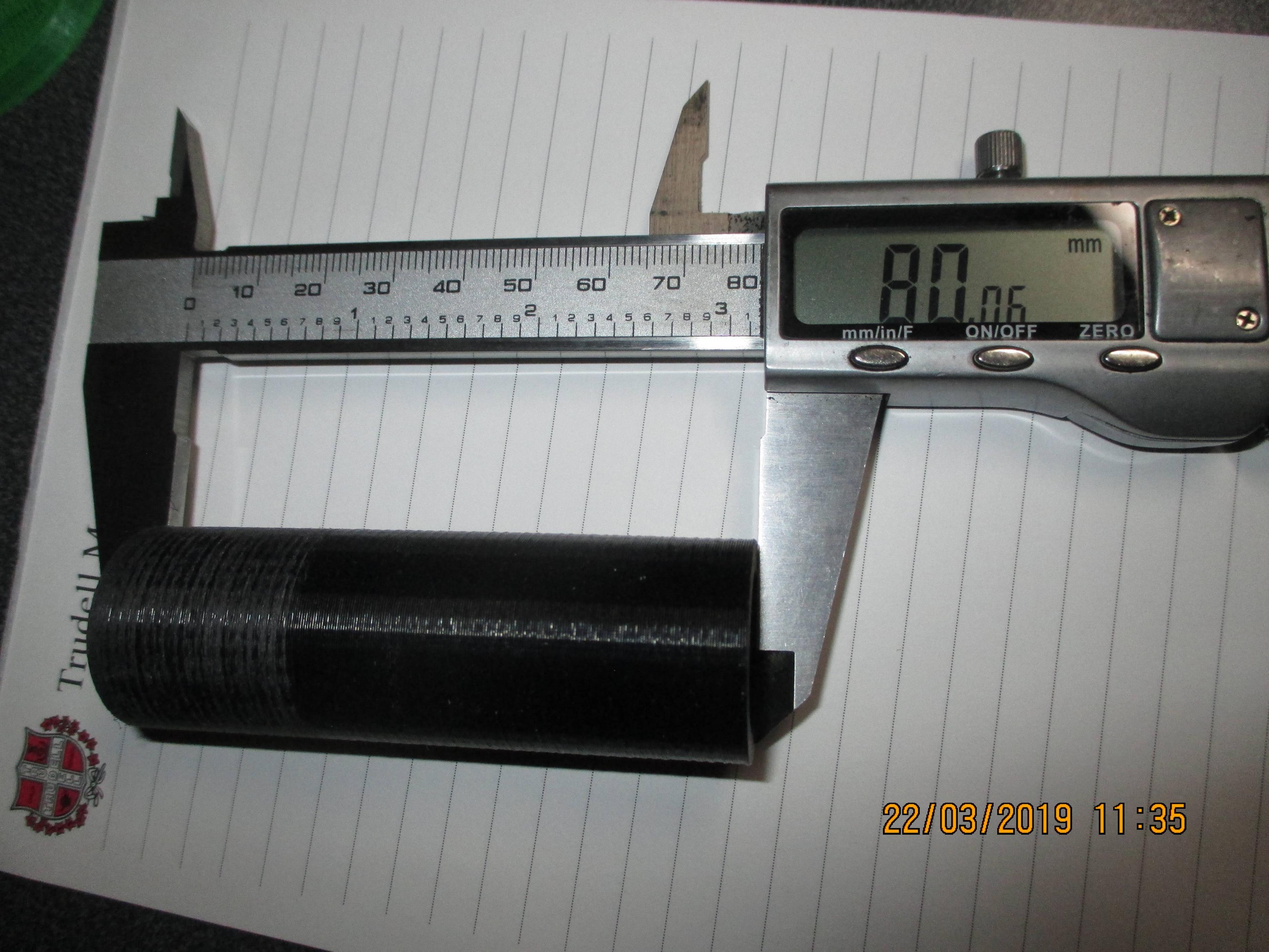
So, theoretically the .2963 layer should reduce the height of an 80mm part to ... (80/.3)x.2963 = 79.01? I this a variable I should figure out for my own printer from doing a test part?
Not exactly how that works
the layer heights have more to do with the number & size of the steps of the motors more than the accuracy of the finished part.
because of that 5/16" threaded rod on Z, (Not metric!) the typical metric layer heights of 0.3, 0.2, etc, do not work as well and can lead to weird layers.
Trust me (and the many others that figured all this out prior to me) that the layer heights i gave you above just work better - unless you are going to go to the trouble of swapping out that threaded rod for a metric one. (not really worth the hassle, imho, but it is an option)
this was printed using the 0.2963 layer height.. and it is about as flawless as you are going to get on an SD..
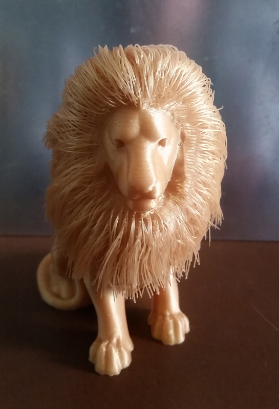
Wow! that is truly an amazing print - done on an SD2 or 3? Any "finishing"?
Wow! that is truly an amazing print - done on an SD2 or 3? Any "finishing"?
done on an SD4 (basically a 3 with a factory enclosure) and other than styling the mane, no other post print processing was done
SoliForum - 3D Printing Community → Buy/Sell/Trade → Looking for Solidoodle 3 aluminum bed support
Powered by PunBB, supported by Informer Technologies, Inc.