1 (edited by Voltt 2018-12-11 10:25:16)

Topic: Connections between Hardware Components: Need Help !!!

Hello,

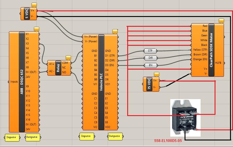
I need some help with confirming if the connections I intend to make between:
   my ABB IRC5 Controller's I/O Card -- Relay -- Velocio PLC (Ace 22) -- ClearPath SDSK Motor
are correct or not?

Details for the components are in the below Links and attached pics:
1.  https://www.teknic.com/model-info/CPM-S … voltage=75
2.  http://velocio.net/plc-control-clearpath-servo-motor/
3.  http://velocio.net/ace/

Pic 1: This is the connections Diagram: x2Scrap00.png
Pic 2: This is the Specs for the DO ports on the ABB controller's I/O Card.
Pic 3: Hardware Specs of the Velocio PLC: x2scrap02.png
Pic 4: Is the model connection made with a different series motor: x2scrap03

Could someone help confirm if my connections are correct?

Post's attachments

WhatsApp Image 2017-12-28 at 5.28.40 PM.jpeg 150.21 kb, 5 downloads since 2018-12-11 

x2scrap00.png
x2scrap00.png 72.37 kb, file has never been downloaded. 

x2scrap02.png 850.72 kb, file has never been downloaded. 

x2scrap03.png
x2scrap03.png 96.12 kb, file has never been downloaded. 

You don't have the permssions to download the attachments of this post.

2

Re: Connections between Hardware Components: Need Help !!!

Okay. 1 set of Connections I'm not sure about are the ones between the Velocio PLC and the Motor. One of the pictures attached gives a sample connection (1) for a different model of Clearpath motor, where all the communication lines and the Power line seem to going to +5V. In my case, the power I want to supply to the motor is 75Vdc ( which is within its operating range of 24-75 Vdc). Are the connections in my setup, correct?

The connections shown in the sample setup (1), are for motor powered with the same +5V. What would be the connection if we want to power the motor with 75Vdc, and still have it controlled by the same Velocio PLC that is powered by 5Vdc?

Another connection that I doubt, is the connection between the ABB Controller I/O Card and the Velocio PLC inputs. I notice now that the COM of the relay should be going to one of the inputs (B1,B2, ...). Apart from that, are the connections correct?

3

Re: Connections between Hardware Components: Need Help !!!

Use the plc to control a solid state DC relay rated for greater than 75 volts and switch the 75 to the motor using the relay.

Printing since 2009 and still love it!
Anycubic 4MAX best $225 ever invested.
Voxelabs Proxima SLA. 6 inch 2k Mono LCD.
Anycubic Predator, massive Delta machine. 450 x 370 print envelope.

4

Re: Connections between Hardware Components: Need Help !!!

I'm sorry, I don't understand... Could you perhaps draw which connections you are taking about?

5 (edited by carl_m1968 2018-12-12 15:29:40)

Re: Connections between Hardware Components: Need Help !!!

Voltt wrote:

I'm sorry, I don't understand... Could you perhaps draw which connections you are taking about?

The below image should work. *IF* the blue, green, white, and black wires are supposed to be at the same voltage as MOTOR V+ and V- for your motor in question.

As long as your 5 volt supply is on the motor and the other wires in red will receive 75 volts from that supply through the relay being controlled by the 5 volt supply. If you need active control of the relay then you could connect it to one of the PLC's outputs that can handle 3 to 10 volts and have the PLC switch it on and off when needed otherwise with this diagram it will be supplying 75 volts any time the 5 volts is on and no 75 volts when the 5 volts is off.

That is a Mouser part number for the solid state relay.

http://soliforum.com/i/?0MML36M.jpg

Printing since 2009 and still love it!
Anycubic 4MAX best $225 ever invested.
Voxelabs Proxima SLA. 6 inch 2k Mono LCD.
Anycubic Predator, massive Delta machine. 450 x 370 print envelope.