Re: Folgertech FT-5
Any updates on this build?
You are not logged in. Please login or register.
SoliForum - 3D Printing Community → 3D Printer Discussion → Folgertech FT-5
Any updates on this build?
actually, I am awaiting a replacement part at the moment.
the hotend mounting block i got was apparently drilled wrong and does not align properly with the where the filament comes out of the extruder (has a mk9 extruder that i really dont like - but that is a completely different issue, lol)
Anyway, the filament doesnt feed into the hotend properly so kind of on hold at the moment...
I did manage to print a 25 x 25mm test cube, and it looks promising enough...but until parts arrive... ![]()
actually, I am awaiting a replacement part at the moment.
the hotend mounting block i got was apparently drilled wrong and does not align properly with the where the filament comes out of the extruder (has a mk9 extruder that i really dont like - but that is a completely different issue, lol)
Anyway, the filament doesnt feed into the hotend properly so kind of on hold at the moment...I did manage to print a 25 x 25mm test cube, and it looks promising enough...but until parts arrive...
Thanks for the update.
I had ordered mine on Sunday, probably wont get it till August though.
what was the estimated ship date when you ordered? Mine was actually shipped the day before the estimated shipping date. ![]()
what was the estimated ship date when you ordered? Mine was actually shipped the day before the estimated shipping date.
July 29
lol, yeah, you have a couple of weeks yet. ![]()
the good news is I got my new hotend mounting block today. Comparing the old one with the new one, there is a difference between them... a couple of minor dimensional differences, but when added together, they were enough to cause issues
now to get it installed and see how well things line up
lol, yeah, you have a couple of weeks yet.
the good news is I got my new hotend mounting block today. Comparing the old one with the new one, there is a difference between them... a couple of minor dimensional differences, but when added together, they were enough to cause issues
now to get it installed and see how well things line up
Well I will be checking in for updates as this should give me some insight into any issue that my arise once my gets here.
hopefully I will have some time to mess with it this weekend. Been crazy busy at work & I am dead tired when I get home - just no energy to do much of anything. ![]()

.
Been crazy busy at work & I am dead tired when I get home - just no energy to do much of anything. hmm
I know the feeling all too well!! This heat has been wearing to say the least.
Tin
.
Been crazy busy at work & I am dead tired when I get home - just no energy to do much of anything. hmm
This heat has been wearing to say the least.
Tin
Try living in Texas.. Days are already breaking over 100..
Carl, I am roughly 1500 miles north of you, and we have been in the upper 80s to mid 90s with high humidity already in June - it is just crazy... =/

Know what all y'all are feelin'...heat index of 105 in SC these days!
at 100 by 9am in Phoenix, tops out at a cool 115.
Hey Heartless,
How is the extruder attached to the rail. I figured it would just be some linear ball bearings but in the instructions it looks as if the mount just slides on the extruder aluminum beam? No bearings at all? Could you please confirm this as I wanted to buy a E3D titan extruder and want to make sure I can still mount it.
Thanks,
Don
the slides have bearings in the little cars that run on them - they can be a bit stiff initially, but a little 3-in-1 oil will help loosen things up.
the carriages screw to the cars (4 screws).
If you find you have ANY missing parts (do a complete inventory when you get the kit), or something doesn't work as intended, do not hesitate to contact Folgertech and let them know (pictures are also useful to them)
Well, got the replacement hot end mount installed - things line up much better now, so that is a plus.
On the minus side, the PCB heat bed is terribly warped right out of the box - so bad in fact that it was pretty much impossible to level the bed properly...
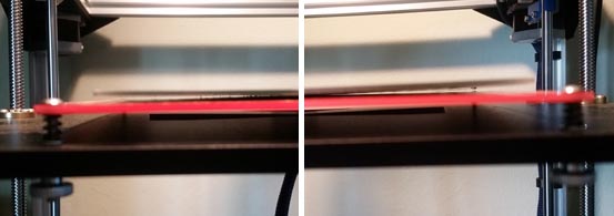
Even using binder clips to clip the mirror tile I use as a print surface to the PCB did not help much... all I have managed to print so far is a 25mm test cube...
So, the other half stopped at one of our local metal shops and picked me up a piece of 3/16" aluminum plate 13" x 13" and as flat as possible for standard plate material. Cost was $12
there are 8 screw holes in the PCB - all were marked on the aluminum and drilled out on the drill press. I also had to carve out recesses to allow room for the solder joints for the power wires - these were lined with kapton tape to prevent possible shorting (the top of the bed also has a layer of kapton).
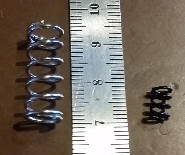
the PCB and aluminum were bolted together using the center holes on each side, then longer screws and heavier springs were installed at each corner for leveling. The stock leveling springs are tiny...
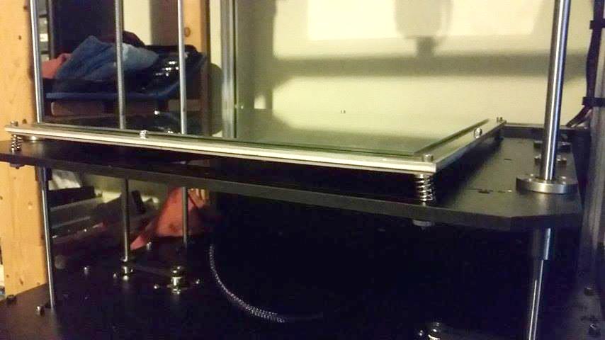
I still need to adjust the Z endstop, and level the whole works before testing, and I may need to increase the vref for the Z axis a little to handle the added weight, but I think this will work... it is definitely flatter than it was! LOL
well, the new bed set up does work, but I definitely need to adjust the vref for the Z axis - it moves ok in the upper range, but it struggles to lift the bed if I go too low with it. (need to pull it back out of it's home to access the board)
One thing I definitely want to address is where the 0,0 point is set - FT, for some unknown reason, set the 0,0 to the right rear, instead of the standard left front. Home is set X - Min, Y - Min, Z- Min (right rear corner and bed up - just like a solidoodle...)
the result is that prints are rotated from what is seen in RH...
I am not real happy about this...
Hoping it is just a matter of making the appropriate changes in the firmware and moving the endstop connectors to the Max positions instead of Min (can someone please confirm?)
Regarding Z, the farther away from the motors the bed is, the less critical the need for good alignment.
Assuming there is some positional adjustments at the base for the location of the Z screws, you could try loosening the mounts a bit and then bringing the bed down, then tightening the screws.
I would think switching to MAX positions would do it...but it's been awhile since I messed with my endstops. They have been my achilles heel ![]()
I went through the alignment gyrations in the building stages - bed down, adjust the lower mounts; bed up, adjust upper mounts; verify by lowering and raising (more than once) ![]()
This thing has a build height of 400mm (on mine anyway - with the taller bed springs & thicker bed plate I lost a little bit, but doubt I will miss it, LOL) Oh, and motors (dual motors) are at the bottom for the Z axis. I think the vref is only at about 0.6v at the moment - from what I have been seeing from others, they are running slightly over 1v on those.
I actually have Friday off, so will most likely spend the day tinkering with it to hopefully get it up to speed. I am going to try switching the endstops to Max and see what happens... being ready to hit the emergency stop if needed, ![]()
I also need to measure it up so I can get some acrylic to make side panels for it.
So much to do, so little time!
I went through the alignment gyrations in the building stages - bed down, adjust the lower mounts; bed up, adjust upper mounts; verify by lowering and raising (more than once)

This thing has a build height of 400mm (on mine anyway - with the taller bed springs & thicker bed plate I lost a little bit, but doubt I will miss it, LOL) Oh, and motors (dual motors) are at the bottom for the Z axis. I think the vref is only at about 0.6v at the moment - from what I have been seeing from others, they are running slightly over 1v on those.I actually have Friday off, so will most likely spend the day tinkering with it to hopefully get it up to speed. I am going to try switching the endstops to Max and see what happens... being ready to hit the emergency stop if needed,
I also need to measure it up so I can get some acrylic to make side panels for it.
So much to do, so little time!
Don't worry, you have until the end of the month to get it right. That's when I should be receiving mine and you will have it all figured out for me :0 lol
Just glad to see someone getting it together and running.
Don't worry, you have until the end of the month to get it right. That's when I should be receiving mine and you will have it all figured out for me :0 lol
Just glad to see someone getting it together and running.
LOL, gee thanks, sandcub. ![]()
There are plenty that have gotten their kits together and running fine, but not without their own minor issues along the way.
The biggest problem with Folgertech kits is they don't do enough beta testing before releasing the kit to the general public, so the bugs don't get worked out beforehand.
With this particular kit, the beta testers had barely received their kits when it was released for pre-ordering. The assembly guide is not fully developed either - it is even titled "draft". This, to me, is the biggest issue with these kits. They get rushed out to market without proper testing or fully developed documentation.
The very first thing you want to do when you get yours is to do a complete inventory of parts - make sure you have everything! Including the hardware - sort & count screws, nuts, etc. Print out the parts list pages of the build guide and check things off as they are verified. If anything is missing, or damaged - email Folgertech right away to let them know. They are usually pretty good about taking care of missing/damaged parts. For any damaged items, take pictures to send in the email.
(make sure the smooth rods & lead screws are straight and true - there have been a couple reports of bent rods)
Next thing I suggest is to clean all of the melamine parts. There is a fair amount of residue/dust from the laser cutting on them and they will turn everything black in short order. ![]() A damp rag will clean them up fine - don't get them soaking wet, however...
A damp rag will clean them up fine - don't get them soaking wet, however...
Then let the fun begin, LOL
well, it is finally up and running, and running pretty well, if I do say so myself...
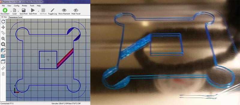
I ran a larger calibration piece last night to gauge the steps/mm for the axis - needs just a little tweaking, but not too badly overall - within 0.3mm at the worst.
the only thing I have calibrated so far has been the E steps to make sure I am getting the right amount of filament in.. and tweaked the vrefs a little.
decided to try something taller today - part of an RC plane wing...
short video here: https://www.facebook.com/northwoods3d/v … 270454152/
and a progress picture
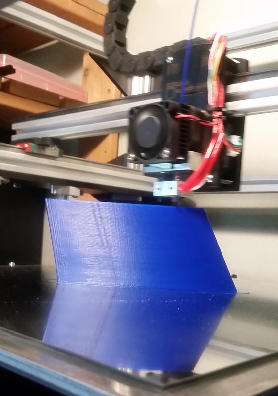
the two lines going up on the left side are from a hole in the model for inserting a CF rod for stability when assembled.
I am seeing a little bit of filament pull artifacts on the side farthest from the spool - really need a better spool holder/location for this beast - but overall I am quite happy with how well it is printing with very little calibration.
current main speed setting is 80mm/s and using my old Prusa print settings for most everything else. 0.3mm layer height, 3 perimeters, 3 top & bottom, and 10% infill
Awesome, still waiting for mine. Is that the stock hotend? and if it is how do you like it. I have an E3Dv6 I was going to use but if that hotend works well maybe I will stick with it. are you planning on getting the CNC and laser cutting addons that they claim will work with this printer?
yes, that is the stock hotend and extruder - it works ok, but i hate the design (fan & heatsink in front of the feed gear - cant see what is going on). Until I can come up with a better alternative for cooling the motor I am kind of stuck with it. I want to eventually swap the hotend out for an E3D volcano setup and I want to be able to see what is going on with the feed gear... I guess I got kind of spoiled on that with the SD4s. lol
I do not plan on doing any of the "add-ons" on this machine. CNC is far to messy for in the house. If I want CNC it will be a completely separate unit out in the garage. Same pretty much goes for laser - a separate machine...
This machine will be a dedicated 3D printer - period. I even eliminated the plug-ins at the E head - everything is direct wired. To be honest, I was not real impressed with the connectors they sent to be used for swapping tool heads.
One person has already had a problem with the heater connector they send in the kit (posted just this morning). IF you plan on getting/using the different attachments - better connectors are a MUST! Especially for the hotend heater cartridge. Several have swapped in XT60 RC battery connectors already. I think they are a very good choice for this application - the wires get soldered to the connector halves and the connection between the 2 halves is solid and firm, yet they are small enough to not be in the way or too heavy.
The Xt60 is a good idea I actually have those laying around.
Thanks for the info.
SoliForum - 3D Printing Community → 3D Printer Discussion → Folgertech FT-5
Powered by PunBB, supported by Informer Technologies, Inc.