1 (edited by caswal 2013-02-16 05:04:35)

Topic: Custom Z Lead Screw

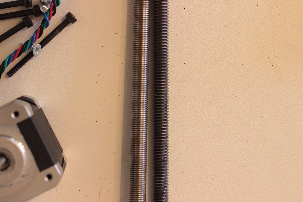
So I got a custom Z Lead Screw made. 8mm diameter, 1mm thread pitch. 15mm long copper nut. With both ends machined to 6mm diameter.

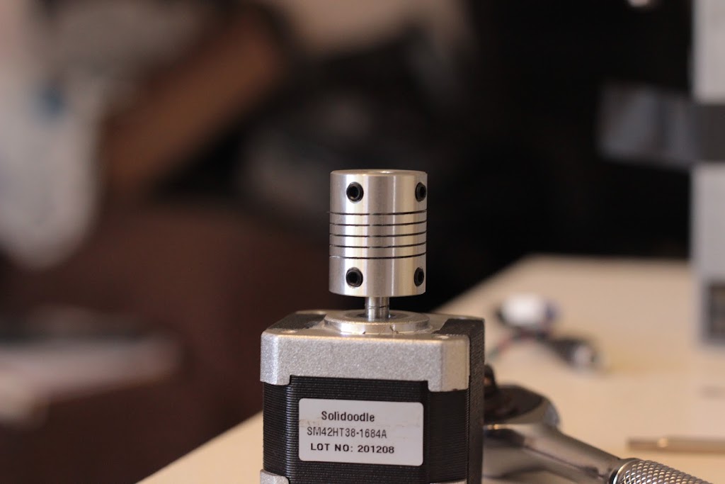
I also ordered some 6mm bearings, and a 5mm to 6mm flex coupler.

Here are the pictures of the screws, new vs old:

https://lh5.googleusercontent.com/-s8RXJl-vmGc/UR8KvE-Z8iI/AAAAAAAABIE/aaDb_fempBM/s1024/IMG_7190.JPG

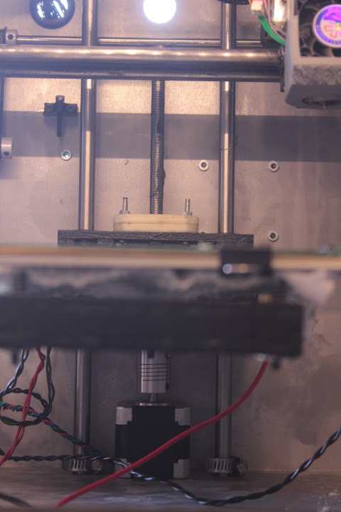
Flex coupler on the motor:

https://lh5.googleusercontent.com/-THFlfcUDOI0/UR8K7NFdFBI/AAAAAAAABGo/FoQcikZetsM/s1024/IMG_7191.JPG

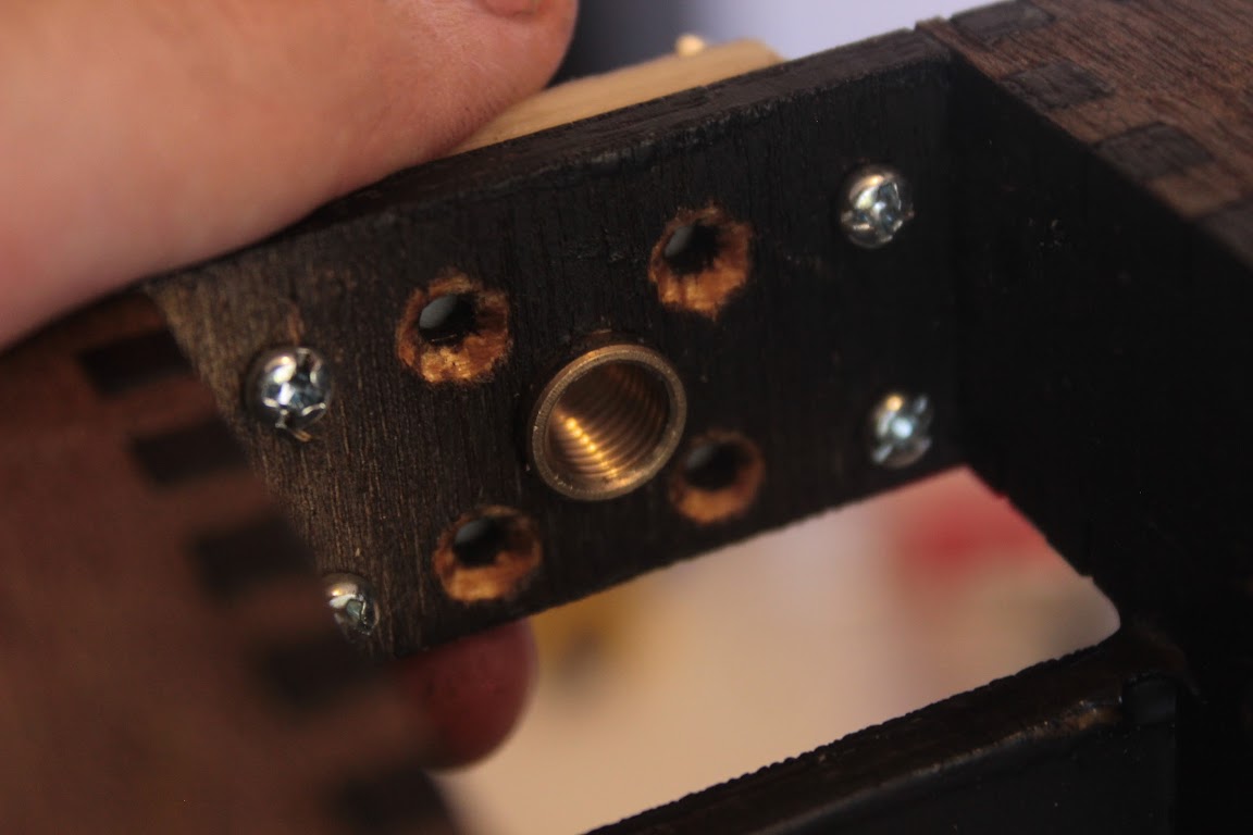
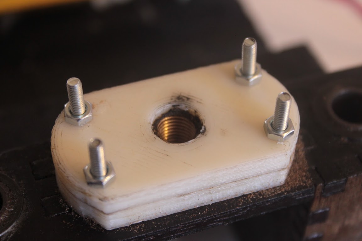
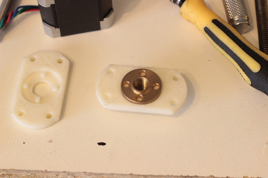
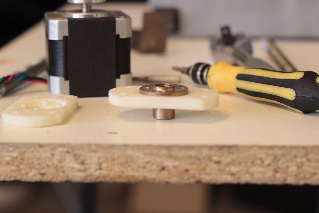
The copper nut, and new fittings to hold it to the bed:

https://lh5.googleusercontent.com/-z_2NjxkTtT8/UR8K9thfh5I/AAAAAAAABG4/Xg-LtzXjvP4/s1024/IMG_7193.JPG

https://lh5.googleusercontent.com/-jAyPit5gPeI/UR8LI1yKERI/AAAAAAAABHI/srwEhDrMXZc/s1024/IMG_7194.JPG

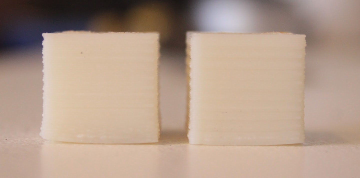
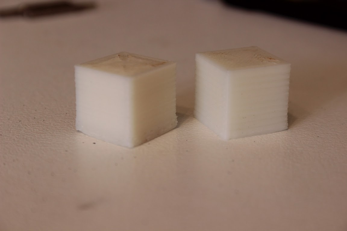
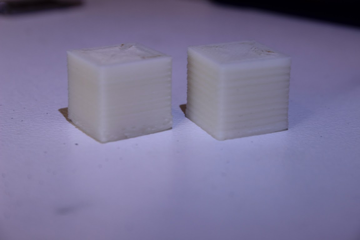
I had some trouble taking some good comparison shots, you can look on my picasa album here, but it has reduced my banding:

https://lh3.googleusercontent.com/-eUTzBo4XSyI/UR8PIoWRrVI/AAAAAAAABIY/bhdiHJDLrLo/s1440/IMG_7199.JPG
https://lh3.googleusercontent.com/-fkSKYxeXxzo/UR8RtQf2fNI/AAAAAAAABIs/49UCNFrBa8k/s1152/IMG_7200.JPG
https://lh6.googleusercontent.com/-KuCP1ZPwxiA/UR8RqWRBnzI/AAAAAAAABIk/KP_Z4XsADQ0/s1152/IMG_7203.JPG


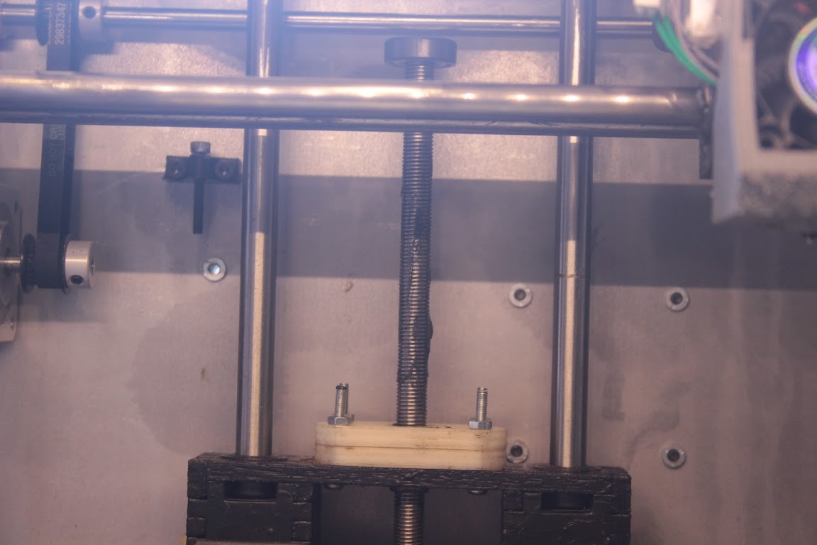
The total cost for all of these parts is about $40. I aim to print a holder, for the top bearing. I have not fixed the top mounts to the print bed yet with bolts, instead I have just cable tied it to make sure it all works. And will take pictures of the complete setup.

Lead Programmer & Co-Owner of Camshaft Software - Creators of Automation - The Car Company Tycoon Game

2

Re: Custom Z Lead Screw

A few thoughts, based on what I have read:

Looks like there's still significant banding, or the same amount.
That coupler is bad news, because it allows for compression along the Z-axis.
Most agree you don't want to constrain the top. Some posts on the issue:

http://www.buildlog.net/forum/viewtopic.php?p=13416

Have you tried the software banding compensation?

3 (edited by caswal 2013-02-16 06:45:06)

Re: Custom Z Lead Screw

It's hard to get a good photo. When you are looking at it in your hands, the banding is a lot better to the point of not being perceivable. It now more looks like x/y backlash than banding on the Z Axis, as what looks like banding on the above photo is only on the corners, the walls have no banding, compared to the old screw that has the sine wave banding repeating every 1.4mm or so. Perhaps I should of printed something cylindrical to compare. This threaded lead screw has a better nut, better threads, and better machined, and has given me markedly improved results.

I really dislike the software fix. It it yet another level of calibration over the top of a machine with a lot of calibration already required. Seems very much a band aid fix to me.

I'm not sure I can really agree that constraining it at the top is bad thing, this new threaded screw is straight, not bent. With the top constrained properly I don't have to worry about the Z coupler compressing.

A few more pictures of the new nut/bed attachment. By shear luck, the shaft of the nut was a press fit into the pre drilled shaft hole in the print bed:

https://lh4.googleusercontent.com/-EXkgZbLWZEU/UR8pmqa6rEI/AAAAAAAABI8/dpNacbc_BUQ/s1152/IMG_7211.JPG

https://lh5.googleusercontent.com/-LsXJsoF_MWI/UR8pqvbPSYI/AAAAAAAABJE/FJ2nt0tYyjQ/s1152/IMG_7209.JPG

Almost the finished result:
https://lh3.googleusercontent.com/-57v5ub-yVoc/UR8p3V1C64I/AAAAAAAABJM/CRC2Wswse9E/s1152/IMG_7212.JPG

https://lh4.googleusercontent.com/-hZ7mRrvjADs/UR8p3qNm95I/AAAAAAAABJQ/txv-KdS_3po/s720/IMG_7213.JPG

Lead Programmer & Co-Owner of Camshaft Software - Creators of Automation - The Car Company Tycoon Game

4

Re: Custom Z Lead Screw

Although I love the idea of the finer thread on the lead screw and the longer drive nut I do wonder about the coupler.
It seems to me to add some possibility of movement in the z axis which is something that the upgraded drive from SD removed for good reason.

If you do indeed constrain the top then having the flex coupler would be a good idea as it would allow the thread to move more at the bottom of the travel than the top which might just make the print better for the majority of cases when you print smaller parts.


I have just thought though are we looking at this wrong. The lead screw is just to drive the bed up and down. If the drive nut was allowed to move in the X and Y axis (via some thrust washers or some such) then you wouldn't need to worry about the lead screw being bent (within reason) as the main supports would be doing their job without any undue pressure to move the bed sideways. As long as the nut removed vertical slack then it should work perfectly.
Does that make any sense? Without having some thrust washers about of the right size I can't even knock something together for a test.

5 (edited by jefferysanders 2013-02-16 13:32:55)

Re: Custom Z Lead Screw

I bet PVC tube/hose would eliminate the rest of those imperfections.

I think it has been observed many times already at this point that flexible coupling can produce better results.  The threaded rod being directly attached to the shaft more easily broadcast the wobble without doubt; a perfect LS/Delrin combo would be machined well enough that you can keep it all rigid...From my research there are really 2  good ways you can handle this problem:  Flexible (like the prusa i3) Rigid (alumantus spelled wrong sry) SD (mixed and bad)...which printer z axis cost the least to reproduce and has the least visible wobbling...yep the i3 with rubber hose couplings.   I have never got around to installing that LS I purchased....I have moved to i3s myself.

6

Re: Custom Z Lead Screw

caswal wrote:

I really dislike the software fix. It it yet another level of calibration over the top of a machine with a lot of calibration already required. Seems very much a band aid fix to me.

As someone formally trained as a mechanical engineer, I can really appreciate your pursuit of a purely mechanical fix, and that was also my first instinct as well  However, as someone who also now works primarily as a software engineer, I also like that a software solution offers some flexibility that you cannot easily get in hardware.  In hardware, you're trying reduce a bunch of periodic error sources to effectively zero (below background noise), so it follows that doing so means tackling progressively tighter tolerances to improve results. 

In the software solution, however, you're just adding numbers to compensate for whatever the periodic error exists, so you can easily add as little or as much compensation as necessary (even overshoot) to get as much precision as you can measure.  The original compensation method--adding a sine curve experimentally--was indeed kind of hacky, but the new custom compensation curve support is sweet.  You simply take 14 depth measurements at .1mm intervals and the gcode inverts the curve those measurements define.  It doesn't solve banding due backlash or horizontal movement in the bed, but for truly periodic z-positioning errors, it can yield effectively perfect compensation.

7

Re: Custom Z Lead Screw

Sorry not wishing to steal the tread for yet another wobble fix but this is the latest post I could find near the subject....but I think I found what I was looking for.

I knew I had seen something that "should" mechanically sort all this z axis wobble out, and help with your custom lead screw fitment.

Not exactly cheap but should be worth a try. I like to work with the theory if it costs more than £1 then it had better be worth it.

Caswal if you replace the flex coupling you have with an "oldham coupling" it should remove any issue with Z axis movement and allow the drive rod to wobble but not influence the bed as it is now only being held in the x/y axis by the drive nut so no force can be transferred to the bed.

Any Z axis backlash will still need to be removed by the larger drive nut but that is a given an yet another topic.


I now return you to your normal program........

8

Re: Custom Z Lead Screw

with you custom lead z axia, i think you need to use this coupling...

seem to remove almost all backlash...

http://jonaskuehling.de/2012/03/15/sugru-to-the-rescue/

9

Re: Custom Z Lead Screw

Haven't had time to really experiment with the Lead Screw as during the week my hot end clogged and caused me a lot of trouble. So this weekend.

I like that coupling ysb, I was going to 3d print a straight coupling myself. The flex coupling is not that bad in the Z axis, so long as you don't use the feature that drops the bed while crossing perimeter. I tested the flex coupling a lot with a dial gauge, and once it has settled down (takes about 0.3mm, which is mostly dialled out in the first layer) you get consistent 0.1mm drops.

Lead Programmer & Co-Owner of Camshaft Software - Creators of Automation - The Car Company Tycoon Game

10

Re: Custom Z Lead Screw

elmoret wrote:

A few thoughts, based on what I have read:

Looks like there's still significant banding, or the same amount.
That coupler is bad news, because it allows for compression along the Z-axis.
Most agree you don't want to constrain the top. Some posts on the issue:

http://www.buildlog.net/forum/viewtopic.php?p=13416

Have you tried the software banding compensation?

Again, as we have said many times before, it is a complicated problem that is not cheap to fix. The best solution in terms of buying a new stepper/lead screw set up is to find a setup with a permanently mated screw and motor, with very high quality threads. This isn't a 100% effective solution either.

Former Solidoodle employee, no longer associated with the company.

11

Re: Custom Z Lead Screw

Has anybody tried to straighten the screw?
Just put it on a sheet of glass,  find the high spots and tap down then down on something soft like wood using a plastic hammer.