26

Re: Firmware Z wobble compensation

Hi Rincewind,

I'm ready to try this update, but I'm not a programmer at all (strictly a geometry guy). So I've downloaded your Marlin firmware package. Is the next step to flash the printer with this firmware? I have not done this since we got the printer in November.

27

Re: Firmware Z wobble compensation

jon_bondy wrote:

Would these corrections be speed-dependent?  That is, would you have to change the corrections if you changed your print speed significantly?

I know of one (non-SD) printer where most of the printing noise disappears as the printing speed increases.  This implies that there is a lot of mechanical resonances (on that printer).

Well, this correction only accounts for the Z axis, and I find it unlikely that you will change the speed on that axis significantly. But I haven't thought about it, I would imagine speed having an effect on backlash but if the threaded rod wobbles you will have an error that is just due to the geometry, and not to mechanical factors. But as we all know, real systems may differ significantly from theory... I'll let you know if I realize something different.

28

Re: Firmware Z wobble compensation

mm2tts wrote:

Hi Rincewind,

I'm ready to try this update, but I'm not a programmer at all (strictly a geometry guy). So I've downloaded your Marlin firmware package. Is the next step to flash the printer with this firmware? I have not done this since we got the printer in November.

Hi, yes, you should flash the printer with "my" firmware. Just follow the official guide, with the package downloaded from my github instead of lawsy's... You shouldn't notice any difference in the printer behavior unless you explicitly turn on the wobble compensation, as my firmware is a direct fork of lawsy's.

Tonight I will post the gcode of some test prints that should help you calibrate the wobble with little hassle, so stay tuned smile

29

Re: Firmware Z wobble compensation

A quick update: I edited the original post by adding some predefined prints that will help you find the correct parameters easily. After upgrading the firmware, Download the zip file and follow the README.

30 (edited by nickythegreek 2013-02-11 00:43:29)

Re: Firmware Z wobble compensation

I suggest checking the calibrations from the Left front side as my my front right had some misaligned layers that are visible in the gcode.

http://f.cl.ly/items/0h2O3E3S0W3c3Y2d2r1Q/Screenshot_2_10_13_7_35_PM.jpg

31

Re: Firmware Z wobble compensation

Rincewind, great calibration set.   I plan to post some images soon. But I am real happy with what I am seeing on this amplitude calibration print!

32

Re: Firmware Z wobble compensation

Using Rince's calibration set, it looks like I will be using:

M97 A0.01 W1.41 P170

I ended up printing out all of the gcodes so that I could see the whole gambit of possibilities.  I'll take pics of each one and throw them up soon as well as some actual prints trying out this setting.

http://f.cl.ly/items/2l3G2W1S0L3J453v0g0O/photo.JPG

33 (edited by justsomeguy 2013-02-13 15:48:46)

Re: Firmware Z wobble compensation

Hi Rincewind,

Thanks for sharing your work with the community.

I'm editing my original begging for help post as I've figured out the problem.  My phase is about 85 and A 0.01.  I had a tough time finding this but once I did, wow!

Tip for anyone having trouble finding the sweet spot.  You might be just outside of the range of the calibration objects.  Look very very closely and you will find where it is better.  Or try printing them again at A 0.01 (gcode samples are at A 0.05) and it might be more obvious.  That would have worked in my case.

Thanks so much!  I'm still dialing it in but my prints have improved almost as much as when I first tried a Z anti-backlash setup.  Single perimeter cube walls feel almost like paper.  It's so cool.

34

Re: Firmware Z wobble compensation

Thanks for the feedback so far guys! I'm glad it's working! 0.1 is quite a wobble you have there... I'm surprised but happy that you found the right parameters.

35

Re: Firmware Z wobble compensation

how to print it at 0.1mm layer when we only have the gcode?

36

Re: Firmware Z wobble compensation

ysb wrote:

how to print it at 0.1mm layer when we only have the gcode?

Unfortunately you cannot. I can send you the stl files if you like, but you would need to add the phase/amplitude increases yourself.

However, the settings that you identify with these calibration prints should also hold at .1mm, even though this layer height is more sensitive to wobbling in my experience. I suggest to get a coarse tuning with the calibration phantoms and then print small cubes (1x1x1cm) at .1mm by varying the parameters around values that you found in order to find the optimal settings.

37

Re: Firmware Z wobble compensation

Rincewind wrote:
ysb wrote:

how to print it at 0.1mm layer when we only have the gcode?

Unfortunately you cannot. I can send you the stl files if you like, but you would need to add the phase/amplitude increases yourself.

It occurred to me that once you've reflashed the firmware, you ought to be able to do your calibration with any object you want without having to muck with the gcode.

Just set the compensation period in pronterface so that the compensation slowly drifts out of phase instead of matching the 18tpi thread pitch.  For instance, if you print a 2" object, the compensation should normally repeat 18*2=36 times.  If you set the period to 1.451mm instead of 1.411mm, however, then it will repeat only 35 times and progressively get out of phase until it is out of phase one full cycle (360 degrees) at the top of the object. 

After printing, you just have to identify the layer height at which the compensation seems to be in phase (i.e. looks the best).  Calculate the phase value:

theta = layer_height * 360 / total_height

and your phase correction value should either be theta or 360-theta, depending on how phase is used in the compensation code.

The benefit is that you can repeat this test with different compensation strengths and layer print depths since you aren't tied to a specific object.

38 (edited by rvanee 2013-02-12 23:49:23)

Re: Firmware Z wobble compensation

I've dialed in the sinusoidal z-compensation on my system recently (after a lot of fiddling over the last month or so). I'm a pretty happy camper.

One of impacts that was very measurable was that, after optimizing the compensation, I had to recalibrate the Extrusion Multipliers for my filaments upwards by 10 to 15%. When the threads are all the same height and width, there is a lot more plastic in a .42mm wall than in a banded wall of the same dimension.

Due to the density increase, I'm guessing that the strength of most parts is increased  after compensation, although I have no data.

P.S. As full disclosure, I haven't yet gone the firmware modification route yet, but am running a home-made script using the "Post Slice Filter" feature in Repetier-Host V0.84 to adjust all the z-values in the G-code as it is generated. (I really had to stretch to remember scripting, but managed)

"Merely corroborative detail, intended to give artistic verisimilitude to an otherwise bald and
unconvincing narrative." Pooh in "The Mikado", Gilbert and Sullivan

39

Re: Firmware Z wobble compensation

Rincewind wrote:

Thanks for the feedback so far guys! I'm glad it's working! 0.1 is quite a wobble you have there... I'm surprised but happy that you found the right parameters.

It was 0.01.  I have yet again edited my original post.

40

Re: Firmware Z wobble compensation

I've been experimenting with determining compensation values *directly* instead of just using trial and error.  I found it very helpful, so here's the procedure I used since I don't have a dial depth gauge:

1) Move the bed to home position and balance a small mirror between the edge of the bed and a stack of blocks or books.  The idea is to have the mirror tilt slightly when the bed moves up and down.  Mine was about 2" across, which is small enough to magnify the bed movement but large enough to still be fairly linear for the range of movement we'll be measuring.  I taped one edge of the mirror to the bed to keep it from slipping.  (see photo, sorry for fuzziness)

2) Mount a laser pointer so it shines off the mirror onto a sheet of paper taped to the ceiling or other flat surface at least a few feet away.

3) Mark the initial laser spot position, and then move the bed down in .1mm increments, measuring each spot.  Measure at least 14 new positions, which covers one full revolution of the threaded rod.  Then go backwards, moving the bed up in .1mm increments until it goes back to home.

4) On the sheet of paper, measure the distance of each mark from the initial spot and write down these numbers.

5) Since we're only interested in periodic errors, we can use any two measurements that are one revolution (14 bed movements) apart as our reference points to scale the measurements.  We can assume that the 14th measurement represents a bed height of exactly 1.4mm since it should have the save wobble as the home position.  Thus, to scale the measurements, multiply each value by 1.4 and divide by the distance measurement for the 14th spot.  The newly scaled values will then equal the Zactual corresponding to each desired Zrod position (.1mm, .2mm.. etc)

6) Chart the difference Zactual - Zrod, which is the error we need to compensate for (see attachment).  In my case, the forward measurements showed a significant amount of non-periodic variability which suggests that I need a stronger spring for my z-axis preload.  The "backwards" measurements, however, taken by moving the bed up, showed an impressively smooth sine-like curve, which we can use compensation to correct.

7) I have yet to test the results, but here's what I've calculated:  The smooth curve in the graph goes from a range of 0 to 0.1 and peaks at about the 9th measurement.  This means we want our compensation curve to have a total range of .1mm and be inverted so that it is lowest when our error is the highest.  Since the compensation curve ranges from -A to +A and has a low point at 270 degrees, then the compensation amplitude for me should be half this, or A = (0.1 - 0)/2 = 0.05mm, and the phase should be 270 - (360 * 9/14) = 38 degrees.

We'll see how it goes when I find some time to reflash and print, but found taking actual measurements really useful not only in determining my wobble compensation values, but also differentiating banding errors due to backlash from banding errors due to wobble.

Post's attachments

CIMG1001.jpg 759.36 kb, 1 downloads since 2013-02-13 

SolidoodleCalib.jpg
SolidoodleCalib.jpg 55.81 kb, 1 downloads since 2013-02-13 

You don't have the permssions to download the attachments of this post.

41

Re: Firmware Z wobble compensation

tealvince wrote:

I've been experimenting with determining compensation values *directly* instead of just using trial and error.  I found it very helpful, so here's the procedure I used since I don't have a dial depth gauge:

That's very cool... Let us posted about how that works out!

42

Re: Firmware Z wobble compensation

Rincewind wrote:
tealvince wrote:

I've been experimenting with determining compensation values *directly* instead of just using trial and error.  I found it very helpful, so here's the procedure I used since I don't have a dial depth gauge:

That's very cool... Let us posted about how that works out!

I just finished my first attempts at using compensation, and I've got to say that I'm stunned how good my prints look now.

As I mentioned earlier, my prints were already very good to begin with, having only minimal wobble, even at .1mm.  By directly measuring the wobble and setting an exact compensation curve, however, I've been able to make it even better and all but eliminated it.  I think this would have been very difficult to  experimentally find a working sinusoidal curve since the wobble was hard to see to begin with, but with direct measurement it was very straightforward.

See the attached before and after photo, where I'm shining a flashlight very low on the surface to maximize what wobble there is.

The only hiccup I ran into was realizing that I had to fix any backlash in the Z-axis before the z-wobble fix could give good results.  Fortunately, using my laser pointer setup while moving the bed up and down made it easy to instantly know when I had sufficiently tightened the spring in my z-axis preload.

I've also been experimenting with a rocking laser pointer mount to make it easy to measure the wobble (without the mirror), and tweaking the firmware to make it easier to set the compensation values without having to do any math.  I'll work on these and post them up this weekend.

Post's attachments

CIMG1009.jpg
CIMG1009.jpg 825.09 kb, file has never been downloaded. 

You don't have the permssions to download the attachments of this post.

43

Re: Firmware Z wobble compensation

tealvince wrote:

Just set the compensation period in pronterface so that the compensation slowly drifts out of phase instead of matching the 18tpi thread pitch.  For instance, if you print a 2" object, the compensation should normally repeat 18*2=36 times.  If you set the period to 1.451mm instead of 1.411mm, however, then it will repeat only 35 times and progressively get out of phase until it is out of phase one full cycle (360 degrees) at the top of the object. 

After printing, you just have to identify the layer height at which the compensation seems to be in phase (i.e. looks the best).  Calculate the phase value:

theta = layer_height * 360 / total_height

I used your method to get the phase and it worked beautifully by printing a 2" tall cylinder. Having a part with no taper built in is best for seeing banding as any slope can hide its affects. The phase precesses around, so measuring from the top of the cylinder down gets you the phase number you need. For me the best looking section was 10mm from the top; so 360/51mm gives you 7.06 degrees per 1mm of cylinder height. So my phase is 70.

Using Rincewind's parts had hinted at 20, and I had been trying to dial-in the amplitude using this phase, to much frustration. I'm sure it's because his layers were building too fast to allow the layers to cool enough (no fan). Using this rotating phase method allowed me to create a large enough layer to build without throwing in a layer cooling variable.

I've got great results now, and just working to get the amplitude honed. Thank you Rincewind for coming up with this firmware tweak, and tealvance for a simple method to nail one of the parameters (I'm leaving the lasers for my sharks).

44 (edited by nickythegreek 2013-02-16 02:20:09)

Re: Firmware Z wobble compensation

Had some issues after I moved my printer, I think my belts and z anti-backlash nut came loose and I had worse banding than I am used to.  So be sure to install a z-backlash solution and tighten those y belts.

I printed out all of Rincewind's gcode parts to see the full gamut of phases.  This zip file has high res images of each block.

http://f.cl.ly/items/2C1J3t3j1S0H3d2D0m2V/Photo%20Feb%2015,%208%2050%2023%20PM.jpg

45

Re: Firmware Z wobble compensation

And one more.  This is a iphone 5 tripod mount from thingiverse that I printed on Octave Gold after tightening my belts, resetting my anti backlash fix.  I started the print without sending rince's M97 command and then I used RH's g-code command input box on the Print Panel tab.  I upped my amplitude value from .01 to .03 this time around.

M97 A0.03 W1.41 P170

I think it is pretty obvious when I sent this command.

http://f.cl.ly/items/421q3v451f3p0Y3R1s1f/photo.JPG

I just want to thank Rince again for his work on this mod!  It might not be the easiest calibration (although I would hardly say it was difficult) but I think the results speak for themselves.

46

Re: Firmware Z wobble compensation

Now those are even layer lines.

47

Re: Firmware Z wobble compensation

Indeed, full res here.

48 (edited by jefferysanders 2013-02-17 18:09:41)

Re: Firmware Z wobble compensation

A0.01 W1.41 P330 for me w/o the ab solution on and looks like a diffrent printer.  This should be part of the all Marlin/Sailfish firmware...it intelligently solves the common issue of using indiscriminately cut cheap threaded rod. This not only helps with the obvious aesthetic issues, but will greatly increase part strength by remedying the root cause of some part failures; the inconsistently fused z layers. This z-axis banding issue is"Solved" now, and I bet SD starts using this before they ship, if not at least the process is easy, straightforward, and gives near perfect results.

49

Re: Firmware Z wobble compensation

The image is kind of fuzzy, but I'm happy to have a completely wobble-free print, or at least as much as can possibly be achieved on this class printer!

Clean Print

To get it, I set a custom compensation curve which I can now quickly measure and enter with the aid of some customized tools and firmware.  Personally, I think it's a lot easier to do than using trial and error, especially since one has to recalibrate every time the z stop screw is changed.  It should also give better results, since it's not limited to a sine curve.

TOOLS:
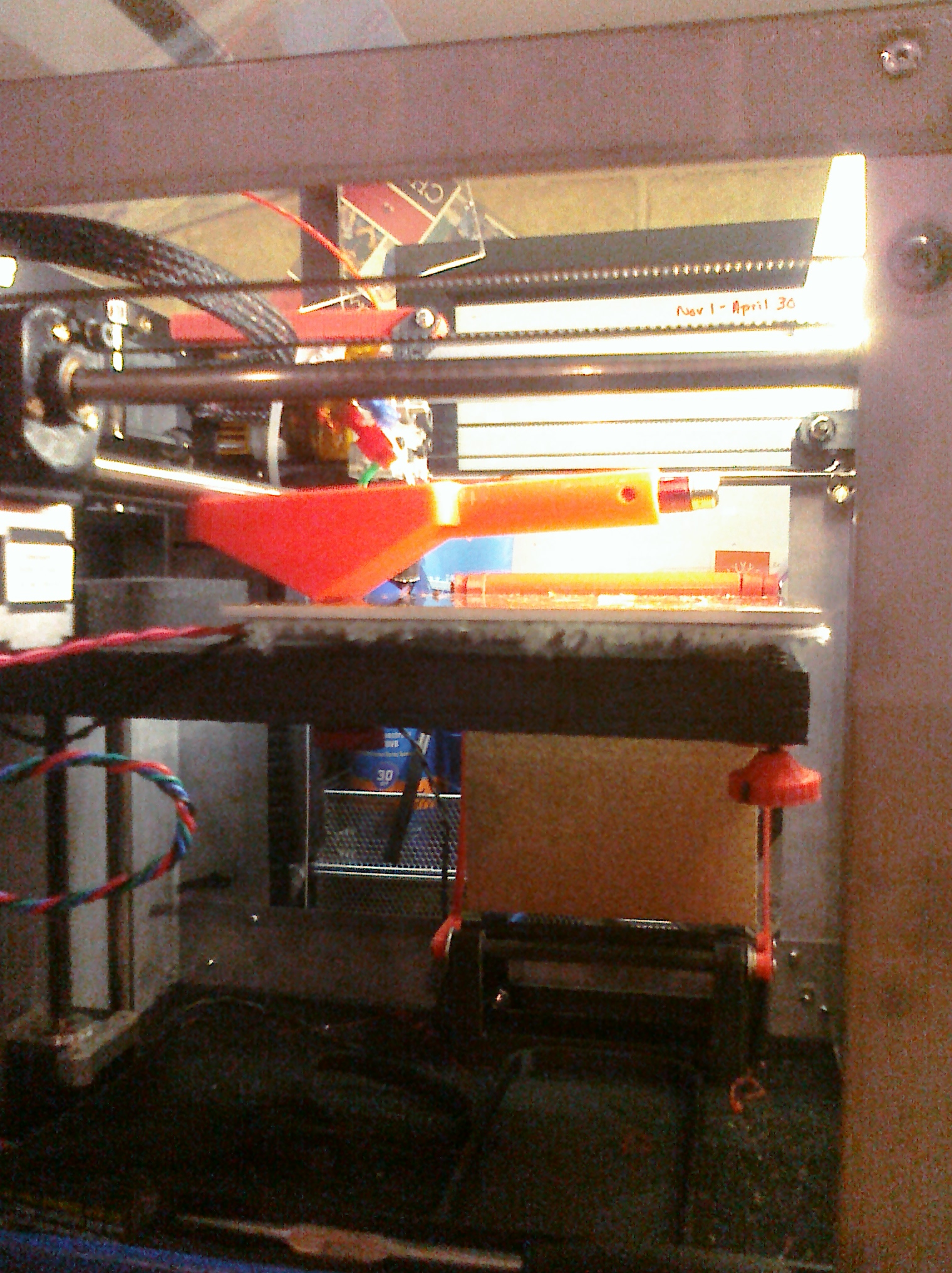
I created a rocking laser pointer mount that is designed to rest on the bed with one end hooked beneath the forward x-axis rod.  By shining the laser on a far wall, the bed movement can be greatly amplified and measured with a ruler.

Rocking laser holder

FIRMWARE:
I modified RinceWind's wobble code to add two small improvements.  First, I added an "L" parameter that can be used much like the "H" parameter when setting a custom compensation curve, except that the values entered can be in any units or scale (such as dimensions amplified with the laser rocker).  The changes automatically calculate the correct scaling factor so one can skip the math to convert laser distance measurements to bed heights.  Next, I added a cheapie graph to the M96 command so one can picture the compensation curve after the values are entered to spot any typos.  RinceWind, what do you think?

PROCEDURE:
1) install the marlin firmware with the modded wobble files

2) print the laser rocker, making any modifications necessary to fit your laser pointer.

3) Home the print head and fit the rocker on the bed with a laser pointer aimed at a sheet of paper taped to a wall about 10-20 ft away.

3) Send the following codes to home the cursor and clear any previous compensation, and move down one full rotation of the z-axis bar:
M97 A0
G28
G1 Z1.411

4) To avoid any backlash, we're starting measurements from one revolution away from home instead of at zero..  First undo any backlash by manually stepping the bed up (head down) a few .1mm steps and then back down (head up) the same number of steps.

5) Mark the first laser point, then make an additional 14 marks, continuing to move the bed down (head up) .1mm between each mark.

6) Measure the distance of each of the 14 marks from the initial point.

7) Use a text editor to enter the 14 numbers into the indicated spaces in the calibrate_antiwobble.gcode file

8) To send the compensation values to the printer, just load the gcode file and select "print"

That's it.  Done.  No iteration necessary; just send the calibration gcode file to the printer at the start of each session, or include it in the custom start gcode used by your slicer.  If recalibration is ever necessary in the future (if printer is jostled or the stop screw changed), restart at step 3.

Hope this is useful.

Post's attachments

calibrate_antiwobble.gcode 416 b, 11 downloads since 2013-02-18 

CIMG1012.jpg
CIMG1012.jpg 1.14 mb, file has never been downloaded. 

CIMG1014.jpg 531.71 kb, file has never been downloaded. 

SDLaserLevel.stl 62.24 kb, 7 downloads since 2013-02-18 

ZWobble.zip 6.48 kb, 11 downloads since 2013-02-18 

You don't have the permssions to download the attachments of this post.

50

Re: Firmware Z wobble compensation

tealvince wrote:

FIRMWARE:
I modified RinceWind's wobble code to add two small improvements.  First, I added an "L" parameter that can be used much like the "H" parameter when setting a custom compensation curve, except that the values entered can be in any units or scale (such as dimensions amplified with the laser rocker).  The changes automatically calculate the correct scaling factor so one can skip the math to convert laser distance measurements to bed heights.  Next, I added a cheapie graph to the M96 command so one can picture the compensation curve after the values are entered to spot any typos.  RinceWind, what do you think?

I like your modifications and your results! It seems that this relatively simple firmware-driven approach is quite successful. And I've seen you did quite a bit of polishing of my code, thanks! smile I was offline for a while, but tomorrow I will double-check your code and add it to the github... Next step will be integrating it in the official Solidoodle repository. I sent a pull request to Lawsy but he hasn't replied yet.