1

Topic: z-axis lead screw replacement

Anyone have any idea the steps necessary to replace this?  I received mine last night (sans any instructions) and on looking at it, it doesn't seem too obvious the steps you have to take to get this thing into place.

I see the bed attached, but the y-axis pulley system seems to preclude removing the bed without removing it first.

Any suggestions would be appreciated.

2

Re: z-axis lead screw replacement

I will be doing this write up tomorrow with some other things if you can wait till then.

3

Re: z-axis lead screw replacement

I can... no worries on that part... then I'll have the rest of the weekend to play!

4

Re: z-axis lead screw replacement

Unscrew the Z motor from the bottom of the case.  Then the whole assembly can duck under the y rod.

5

Re: z-axis lead screw replacement

Would I need to remove the bed too?  Or would removing the endstop and then unscrewing the rod be easier?  Or even feasible?  Don't want to do too much to it, but don't want to gank the thing into non-working status...

6

Re: z-axis lead screw replacement

You would need to remove the bed, but you don't have to take it out of the printer beyond the reach of its wires.  Loosen the hose clamps on the guide rods and slide them out the top or bottom until the bed comes free.  Then you can move it to where there is room to unscrew the threaded rod from it.

http://solidoodletips.files.wordpress.com/2012/09/photo-29.jpg

7 (edited by jefferysanders 2012-12-15 00:12:19)

Re: z-axis lead screw replacement

It is easier than it looks/sounds. I have been taking mine apart all week testing different backlash solutions that I have been printing.

8

Re: z-axis lead screw replacement

jefferysanders wrote:

It is easier than it looks/sounds. I have been taking mine apart all week testing different backlash solutions that I have been printing.

I look forward to reading about that. I hope you'll be sharing on the forums ^_^?

9 (edited by cckens 2012-12-27 02:12:34)

Re: z-axis lead screw replacement

Just replaced the z-axis lead screw.  Took 3 nuts to pop that thing off as they had it really firm on the motor.  Only had some basic superglue, but it seemed to have done the trick... (more on that one in a bit...)

Replaced everything, re-leveled the bed and started a print.  Went with the hinge piece that showed the banding so well in the past. Result shown below.  On the right we have the original lead screw print, on the left the new one.

http://www.kenzden.com/download/PartCompare-a.jpg

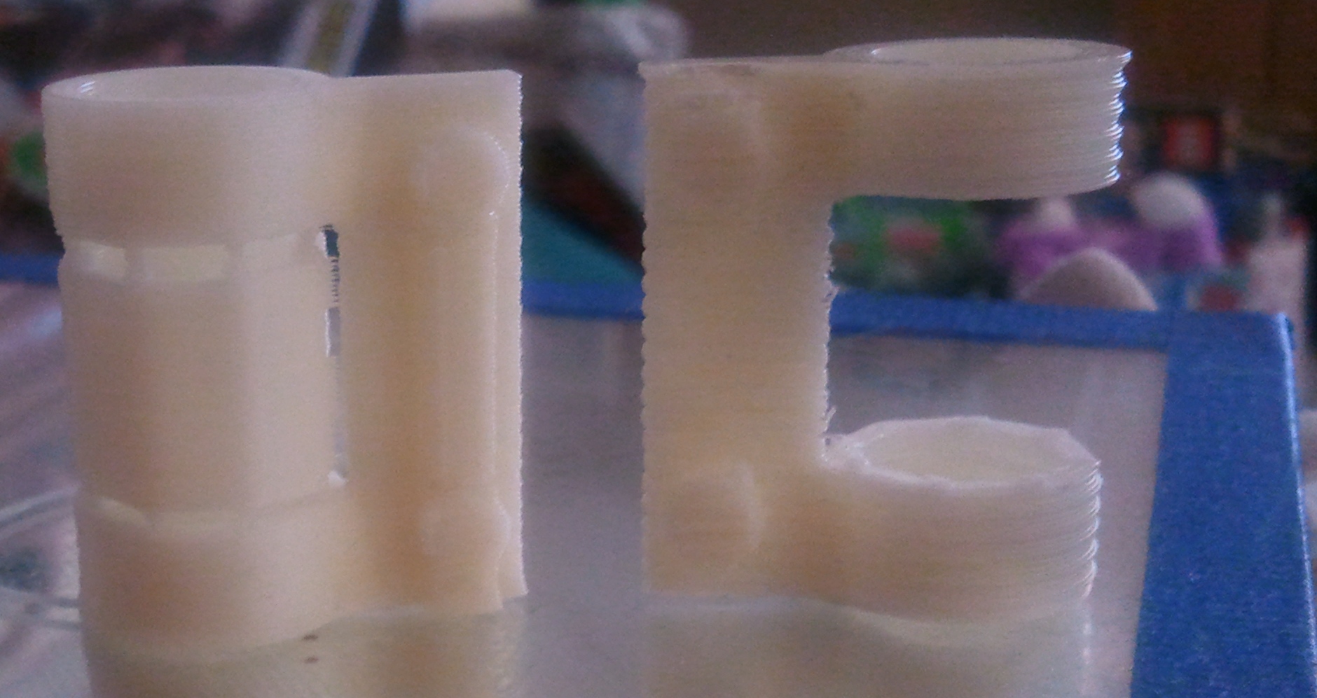
As you can see, there's still some banding, but it's minimal at best, and could be caused by backlash.  At this point I grabbed the jam nut and attached it to the lead screw.  figured that if it could hold for a bit, I'd try a couple of small prints to get a better view...

Not so good.  I ran the gcode and all of a sudden on a z-home I heard the grinding of the motor then a kind of spinning sound, but no movement on the z.  The superglue had popped and the screw is spinning on the motor.  Now I get to do it all over again, this time with some better adhesive and maybe a bit more grease.

BUT!!!  I know that the lead screw has solved most of my issue with the prints

Post's attachments

PartCompare-a.jpg
PartCompare-a.jpg 492.91 kb, 2 downloads since 2012-12-27 

You don't have the permssions to download the attachments of this post.

10

Re: z-axis lead screw replacement

Is this z-wobble issue only found on early printers only or on every single one being produced now?

11

Re: z-axis lead screw replacement

I received mine in early November, so mine is not part of the early batches.  However, this can conceivably happen in newer AND older machines as well.  The degree that I encountered was more severe than is normally seen in any of the models.  Replacing the lead screw seemed to be the best (and most cost effective) option.  Solidoodle provided the lead screw (free of charge) but I had to pay for the shipping.  Fair trade.

12 (edited by shabby 2012-12-27 03:07:50)

Re: z-axis lead screw replacement

My printer should be here next week, i hope i won't run into this issue. If i will you can bet the sd3 will have the same issue since its the exact same design.
Tell me how thick is the bottom panel that the z-motor is attached to, is it thin and flimsy and bends easily?

13

Re: z-axis lead screw replacement

As I said, mine was rather severe.  Printing a couple of calibration objects and you can pinpoint a few problems and this is one of them.  You can also see a few signs of a bent lead screw without even printing.

The video here (http://www.soliforum.com/topic/672/zaxi … er-wobble/) shows the base flex that you get.  The stepper is screwed onto sheet metal so some flex is expected.  Run the z-axis down 100mm and then home it. If you see the top of the screw wobble outside a couple of mm you'll see problems when you print.  I did.

Can't tell you how thick the base is, but it looks like all sides are 1.25mm thick.  The frame is strong enough to hold quite a bit of weight.

14

Re: z-axis lead screw replacement

I was also thinking of replacing the threaded Z rod (and keeping my existing motor).  How exactly is the rod attached into the motor?  Is it just press-fit to the motor shaft?  I see someone mentioned using 2x nuts, are they saying to screw them down till they press against the motor body itself and force the rod out?  (I have the new/improved design with no coupler)

I am planning on replacing it with a high-precision metric threaded rod, obviously this would involve adjusting the firmware/EEPROM setting for Z steps per mm but I assume this would be the same basic technique as the extruder calibration (tell it to go 100mm, measure the actual travel, then calculate the difference)?

Thanks
SLAM-ER

15 (edited by shabby 2012-12-27 16:10:35)

Re: z-axis lead screw replacement

cckens wrote:

The frame is strong enough to hold quite a bit of weight.

Enough to stand on, I got a chuckle out of that engadget sd3 video, who stands on their printer while printing? Its strong for that but the base floor is thin and flimsy. When i get mine i think i'll put a 1/4" or 3/8" thick sheet of aluminum on the floor, make some cutouts for the z-rods, secure it with some bolts and attach the z-motor to it.
Otherwise a forged lead screw should solve this issue.