1 (edited by jooshs 2012-12-16 16:05:03)

Topic: Z axis wobble

There has been a lot of discussion here and over at

https://groups.google.com/forum/?fromgr … 5YwtCbzw0o

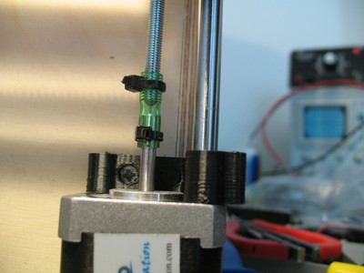
There has been a lot of concern about it possibly being a software/firmware/resolution issue.  I don't know how many people have taken the time to closely inspect the z motor in use, but I think we should put to rest anything but play and slop between the leadscrew, motor, and bed.  Here is a video that clearly shows the rocking of the z motor.


With the old design, I was able to basically eliminate banding with the design  near the top of this thread.

https://groups.google.com/forum/?fromgr … S8Anfz6QwJ

I haven't tried this one yet, but it seems the most promising. 

http://www.thingiverse.com/image:193181

I really believe the problem lies in somehow eliminating nearly any slop in the x and y axis with an emphasis on the x.  One other solution I am tinkering with is to attach some runners to the front left and right corners of the bed.  These would be spring loaded into the corners of the frame and run up and down the frame corners via the spring loaded bearings.  Still a huge work in progress, but I will post as I attempt different solutions.

2

Re: Z axis wobble

I think the idea of using a piece of tubing as the coupling is worth pursuing.

http://solidoodletips.files.wordpress.com/2012/12/img_7901.jpg

This would allow the Z rod to be completely unconstrained in X and Y so it can't push the bed, the motor, or anything else around.

I've been trying to think of something to stabilize the front of the bed.   If the movement of the bed is possible due to the tolerance between the guide rods and the bushing, is there a way to take up that slack?  I don't know if it would be possible with the current bed, but what if there was something between the bushings that can apply outward pressure against them so the rods stay in contact with only one side of the bushing?  I don't know what they are called, you know the metal loop with threads on either end with bolts in them.  As you spin the loop the bolts are drawn inward or push outward.  There is also the gap between the guide rods and their holes- that can be taken up by the bracket that Ben Trigg designed.

3 (edited by Cwalster 2012-12-16 18:33:42)

Re: Z axis wobble

Turnbuckles are what your talking about. I could see that working, though if solidoodle used reasonable quality bushings its probably unnecessary. I see the bed moving more because its cantilevered so far away from the rods, it may even be flexing the rods themselves. You may be able to add a pair of rods at the front to help support it.

4

Re: Z axis wobble

I was having a hard time wondering where all of the banding issues came from when the printers started shipping in earnest.  I never experienced them to the extent I saw in a lot of the pictures.  The banding I had was very minimal and could be smoothed away easily, but I wanted that to improve.  So Solidoodle sent me the new axis, which I thought was supposed to improve the banding.  However, much to my dismay, the banding is waaayyyy worse with the new z motor and axis.  Even though my old threaded rod was very visibly not straight, it provided much better prints.  I can't believe how much worse they are now.  Therefore, I salvaged the old z assembly and reinstalled it.  The old rod was one inch taller.  These side by side prints show the drastic difference.  Black is not the best quality printing material or easiest to see, but the results here are very clear.  Something about the new assembly is definitely causing the banding, at least in my case.  Both assemblies were supported at the top with Ben Trigg's design.  The only difference immediately visible is that the longer rod supported up one inch taller reduces the banding. I wonder if Solidoodle would be better off extending the z rod all the way to the top of the case and having it run inside a bearing up there so that they can control the tilt of the z axis.  I think I will try this modification when I get a chance and find a good way to mount the bearing or bushing.  I know Ian was looking for a way to do this on the y rod so any suggestions would be great.

http://farm9.staticflickr.com/8352/8285427196_64dd84faea_b.jpg

5

Re: Z axis wobble

Were these both printed at the same speed with the same slicer? 

I have a very tiny .1mm print (solidoodle natural filament) that I did right after solidoodle released the slic3r program was released and it seems to have no visible banding while almost all my other larger ones at least has some visible banding.  It was probably printed at 10-20mm/sec.

My larger .1mm print of the same stl has very prominent banding.  It went through a acetone vapor run which completely smoothed the surface but the banding shows through the model from previous layers (something you cant see with the black filament). 

One of the key setting differences between the 2 scaled prints were outer shell count and infill. Could adding more shells increase banding visibility?

It seems to me that there are some hardware issues that can cause banding, but that they can become more pronounced with software settings like flow rate and print speed.

6

Re: Z axis wobble

These 2 prints were done with exactly the same g code files back to back. You are correct in stating that more shells and possibly more infill will increase banding. However, this difference is extreme. I never had an issue with banding till this last week when I installed the new axis. It is night and day as in I never saw anything resembling this banding with any configuration before installing the new z assembly. The only other person I know who went from the old to new assembly is Ian. I am not sure if he experienced the same immediate difference.

7

Re: Z axis wobble

Do you think that there's a way to add a coupler to the z-axis that may give you that clearance?  I know that the coupler was an issue with some, but if it's extending the z to a bearing-control, would this increase performance?

8

Re: Z axis wobble

My replacement was an improvement - http://solidoodletips.wordpress.com/201 … rs-part-2/

I was also wondering about the banding because it seemed almost universal with the newer printers, and we didn't see it at all before maybe late October.  At the beginning I was the only one who had any banding, and that was because it didn't show until you printed .1mm layers.   I wonder if they found a cheaper source for threaded rods and got lower quality as a result.   Is there any difference between them that you can see?  If the problem is with the threads, I don't know if it would be anything you could detect. 

Differences in settings might affect how pronounced the problem is, but I think it has to be the rod.  If the new one is straighter, but worse, then I think it would have to be the threads rather than wobble.  Also I think the bracket at the top might make things worse.  If the rod is bent or wobbly, and constrained at the top by the bracket and the bottom by the motor, then that wobble has no place to go but the bed.

9 (edited by jooshs 2012-12-18 21:13:06)

Re: Z axis wobble

Not sure, I tried something similar to that and it didn't work well at all.  I tried using an extended coupling with a bolt running through a bearing right next to the top.  The bolt was long enough that it met up with the z axis and the coupling was a 1.5 inch long nut.  It seemed like it should keep the wobble from occurring, but didn't.  I'm a little stumped to be honest.

Ian, I am not sure about the threads.  Just on a initial feel test, the 5/16 nut seems slightly looser on the new one, but I will do detailed measurements with calipers tonight.  If the rod is secured at the top, I don't think the play goes to the bed, I think it goes to the motor connection.  That is why in my video the motor rocks back and forth.  I'll be interested to see the difference in the measurements.

10

Re: Z axis wobble

Ian,
It may be worth testing to see if you get the wobble translation to the bed with the top bracket.  May have to design and print a bracket to try to keep the wobble at the top down.  Haven't had time to install the new lead screw (darn you Xmas shopping!) so it might be worth exploring now before replacing screw.  I can at least print something workable, and it may work.

11

Re: Z axis wobble

My Z screw is straight and stable at the top now, but with the old one I didn't see any difference with the bracket at the top.  It stopped the end from wobbling, but the back and forth motion visible through the "window" at the back of the Z carriage was the same, and the print was the same.  I do think the bracket has some value in keeping the guide rods tight against the edges of their holes, to elimate one more potential source of wiggle for the bed.

12 (edited by ysb 2012-12-18 22:52:48)

Re: Z axis wobble

i will do the test to mount again my old z screw when my current print will be finished... i'm like jooshs... i think that i had less banding with the old screw than with the newer screw.... (i'm sure with the 0.3mm profil... less with the 0.1mm)

13

Re: Z axis wobble

Joosh: are you actually SEEING wobble in the Z axis screw while you print?  What about when you put the bed all the way down and then Home?  When the Z screw is running in the latter case, I really can not see ANY wobble in the screw at all.

To check whether the threads are consistent, you could try mounting a dial indicator on the extruder and then commanding the Z axis to go down 0.1 mm at a time, and see what your readings are. You could plot the expected reading vs the actual readings to see if you can spot the wobble in the Z values on the graph.

I have never had a Z axis problem, with either of my printers, so I cannot comment from experience

14

Re: Z axis wobble

The dial indicator would be a good comparison test between the screws.  Set something on the bed under the indicator so you can try it a positions other than 10mm from the nozzle.

15

Re: Z axis wobble

If i do not have the brace up top, i can see it wobble. I will check out the z measurements. I was previously under the impression that the wobble was caused by clearance in the nut and the threads in the xy plane allowing the z rod to push the bed around. It sounds like you guys think it is more from inconsistencies in movements in the z due to inconsistent tpi values that I'm assuming would be consistently inconsistent?  This is why I thought maybe the new rod had more banding. This is driving me nuts and I will get to the bottom of it. If there is an inconsistency in z movements, you should be able to edit the g code with a sinusoidal periodic error correction curve function. I have dealt with this kind of minuscule error in astrophotography which is one of the only things I can think of driven with steppers in hobby activities that require this kind of precision. Ian, do you think we could get the developer of slic3r to create an error correction function g code command?  It would have to correct the z steps, but allow the extrusion commands to remain the same as if the z steps were staying the same.

16

Re: Z axis wobble

How thick is the floor that the z-motor is attached to? Seems like its bending under load and causing the motor to rock back and forth with it.
Perhaps attaching a thicker sheet of aluminum/steel to the bottom of the floor/z-motor won't allow it to move anymore.

17 (edited by ysb 2012-12-22 22:16:43)

Re: Z axis wobble

i quote myself..

the test is done, and i can confirm that the old z screw (with the ABS coupling) do a better job than the new one.

nearly no banding with the old, with the same Gcode, same speed, same hardware configuration (apart the z screw)


it's incredible that an 'update' do a far worst job than an old part... sad


ysb wrote:

i will do the test to mount again my old z screw when my current print will be finished... i'm like jooshs... i think that i had less banding with the old screw than with the newer screw.... (i'm sure with the 0.3mm profil... less with the 0.1mm)

18

Re: Z axis wobble

Stiff and Rigid seem to be enemies for this type of leadscrew setup...you want to send that wobble anywhere  but the bed if you can...I posted how that could be done awhile back.  Zip ties and UPVC tubing to absorb the wobble as done on the prusa 3 and other  prusa/mendals.  I can't get my leadscrew off the motor...I have tried 2 nuts and that did not work,  I don't want to heat it up as my threaded rod is straight...time to order another motor.