Topic: Modelling Basics
EDIT: 2/19/2013 - Modeling Techniques updated
I’ve been seeing a lot of posts on modelling and how a model isn’t really slicing the way that they want it. I’ve been wanting to write a primer on how to get a model ready for slicing when you create it. A lot of people aren’t conversant with 3d software, or get bogged down with the terminology when coming across the forum, so here’s my take on it.
It’s a work in progress, folks as I have 3 kids, a wife and a job, plus the “infernal machine” to placate, so bear with me. I’m getting to it as fast as I can. The modelling section should be completed in another week or so, the Fix section, another week after that. So feel free to comment. I only hope that I’m not getting stuff wrong, but from the way that I’ve been outputting my own models, I think I’ve got most of it right.
*****************************************************
We’re all here to create things... That’s why we got this infernal contraption to begin with. I say “infernal” and should use “miraculous” instead, but I won’t. Why? It’s pretty easy to document. Let’s face it. We’ve all come across a dilemma that plagues our being; getting our ideas out of our head and onto the machine. For some it’s simply a matter of using a CAD program and letting it all hang out. Those are the lucky ones. Ones with a background in crafting real-world objects and milling them out of solid real objects. These designers have it easy as they have the experience to “create” what they want. What about the rest of us? We model and wonder why we get errors when slicing the file. That’s why I felt the need to write this.
Now, I’ve had a background in 3D modelling for about the last 8-10 years. A hobbyist who tried to keep his skills updated so that he could create virtual objects of things that interested him. A goodly number of us fall into this category, I’m sure.
But creating virtual objects is not the same as creating objects in the real world. Virtual objects don’t object to intersections of mass, or multiple faces on the same plane occupying the same coordinates. Have I lost you yet? If so, then I may be able to help. I’m going to make this as painless as possible. For those not lost, don’t despair, there’s stuff in here for you, too!
Virtual modelling is an art form in and of itself. It involves imagination and creativity to put together shapes into virtual real-world objects. We use all manner of objects from 2 dimensional and 3 dimensional to craft a likeness and then we render that object in all it’s pixelated glory for all the world to see. Glorious! but flat.
Modelling real objects is very similar to this except your output is now 3 dimensional. You take the same shapes and combine them to make an object that we use our machines to “print” real. The devil lies in the details. No, not the fine shapes of the object, rather the details that make real object behave to real physical laws. Let’s explore this, shall we?
Assumptions: The following is assuming that you are using a program that allows for manipulation of individual points (vertex/vertices). Wings3D, Carrara, Blender, and Hexagon3D are examples of vertex based modellers, though Carrara has a few other modelling types at it’s disposal. Lightwave and Rhino rely on NURBS surfaces which are entirely different animal and has limited bearing on vertex surfaces as any STL derived from these models is converted into vertices. The individual unit of vertex modelling is the facet. A facet is composed of at least 3 connected vertices forming a triangle. There can be more, but the triangle is how most slicing software treats the STL files contents.
Mass Interaction
In the virtual world objects exist without any coherent mass, (this is, unless your program supports collision physics) free to move about in any direction over and through other objects. The real world shows us that if an egg collides with the floor, the egg breaks. The shell is an object that has definitive properties of edge and thickness in addition to a contiguous surface (which is called being “manifold”) and this is what we must remember when modelling objects for printing. Even broken, the parts all have these properties and are manifold on their own.
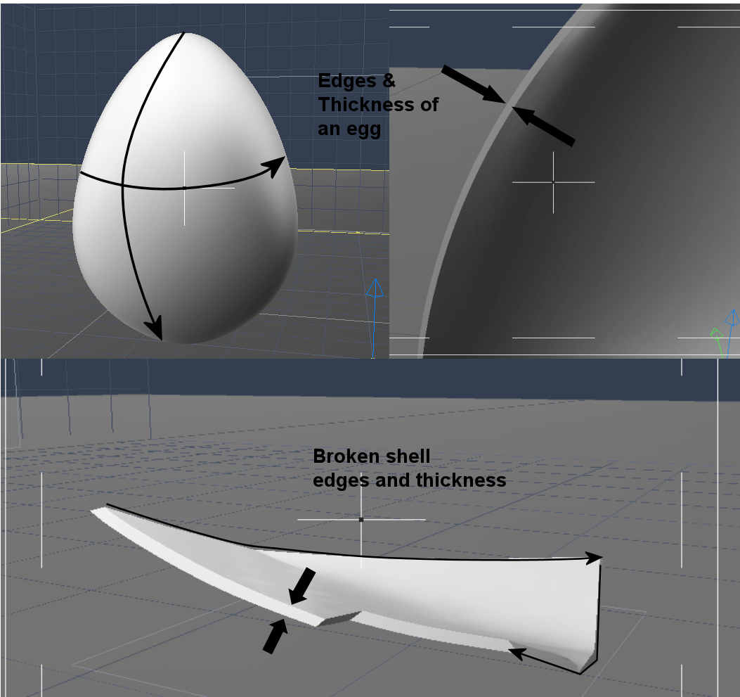
(Image: Egg Shell cross-section and broken shell piece cross section)
Manifold surface
A manifold surface (as mentioned previously) is a contiguous surface, meaning that there are no holes or defects in the surface. This does not mean that your object cannot have a hole. It just means that if you model a hole, the surface must be complete around and through the hole making the model watertight. This can be by capping the hole with a set of facets to create a depression or by going completely through the model creating a hole surrounded by facets.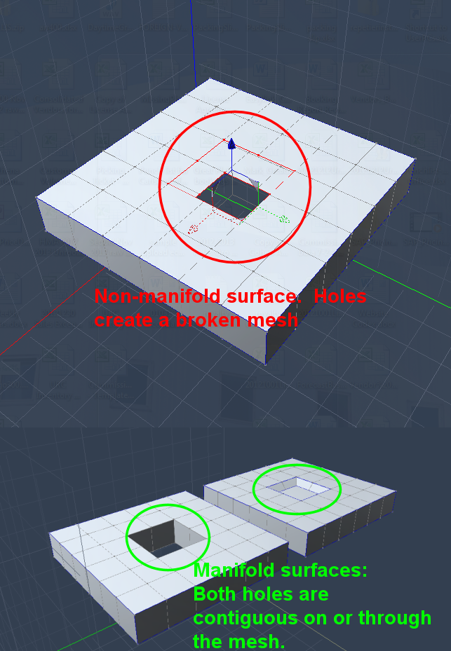
(Image: Contiguous, non-contiguous hole)
Manifold surfaces must also be non-intersecting. A single vertex may have many connections within a surface but they must all lie with the same surface and cannot connect with another surface without intersection of the surface by at least 4 contiguous facets (forming a box or tunnel of sorts).
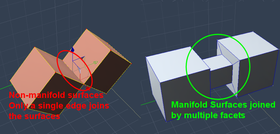
(Image: Intersecting vertices/facets, non-intersecting vertices/facets)
Facets can also be self-intersecting, but this is much less of an issue for slicing programs. A self-intersecting facet is one in which it overlaps another facet. Such a facet covers or is covered by another facet thus conflicting the surface. This is only an issue if the facets “break” the surface contiguity by creating unresolvable overlap. This overlap confuses the slicing program and will cause it to error by either “mis-slicing” the mesh, or not slicing it at all resulting in a blank screen in the slicing program.
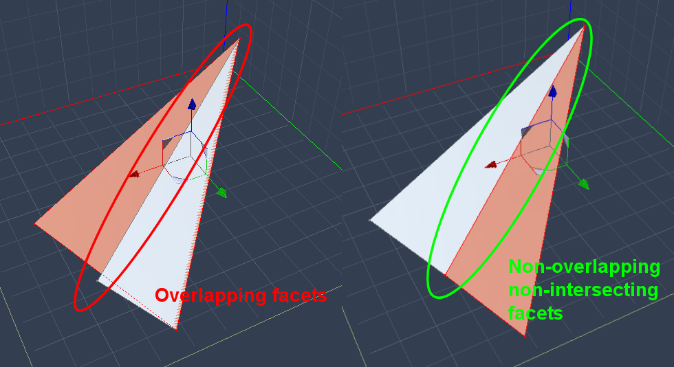
(Image: Facet self-intersection)
These types of self-intersections don’t normally happen and we’ll look at ways to avoid them, or at least detect where they are to fix them.
Modelling Basics
There are many ways to model an object and I am hardly in the position to teach you all of them. Rather I can show you the styles that works for me and let you experiment on your own. The techniques I will show will lend themselves to modeling simple to more complex items, and should be compatible with any vertex-based modeling system.
Tracing
Tracing is probably the most simple way to create new objects. If you have an image of an object that you want to create, it’s usually a simple matter to import the image into the modeler (provided your modeler supports this, most do) and trace the outline(s) of the object(s).
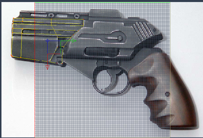
(Image: Traced outline of a BSG pistol from the first mini-series [image from http://karltate.wordpress.com/])
But tracing will not give you a fully printable 3D model. It will only give you the general shape of an object/objects but it’s usually a good launching point for creating the 3D object. Which leads us to...
Box Modeling (Extrusion)
Box modelling is the process by which simple objects are used as the basis for more complex vertex meshes. As the name implied a simple box or cube is used to start the model (though any object can be used). From there, the faces of the box are expanded by pulling/pushing (called extruding) the facets out/in and resizing. Here’s a basic progression from box to complex object.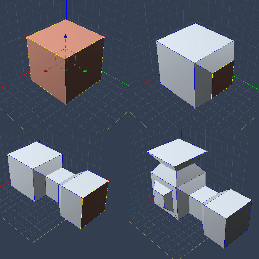
(Image: Box Model progression)
Our tracings can also be used to create a more complex object. By extruding the traced object out and then extruding various faces in or out we can create a rather sophisticated model quickly.
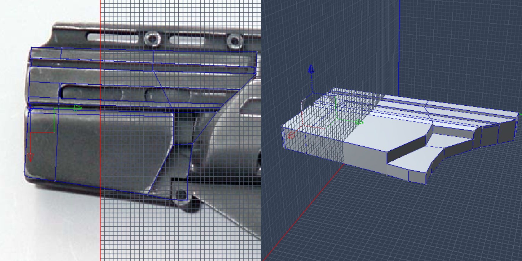
(Image: More complex object from the traced gun barrel)
Box modeling is the simplest way to get to a more complex model. It requires little effort to accomplish change and further techniques can refine the model even more. This is the method that I use most in creating models as it requires little time to get your basic shapes into place.
Lofting/Blending
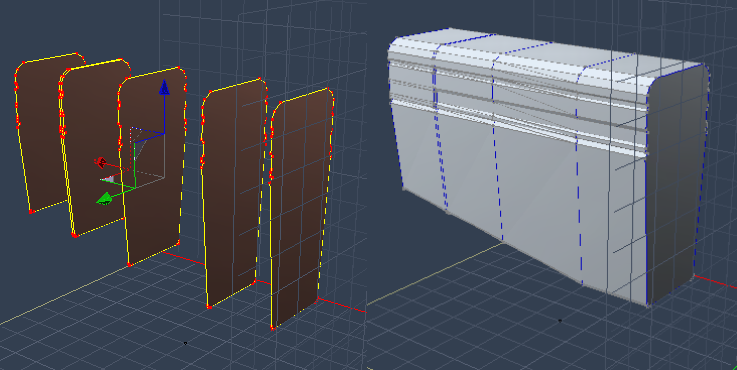
Sometimes modeling from a simple box to a complex shape would take too long. For instance, you wanted to create a boat. You have plans that you’d use that show the boat cut up from the side into pieces of cross section. These shapes are easy to trace, and can be put to use to create the profile by using a process known as lofting or blending. By setting the traced cross sections in order from front to back you use the software to loft these cross sections together creating a skin that forms the body of the boat.
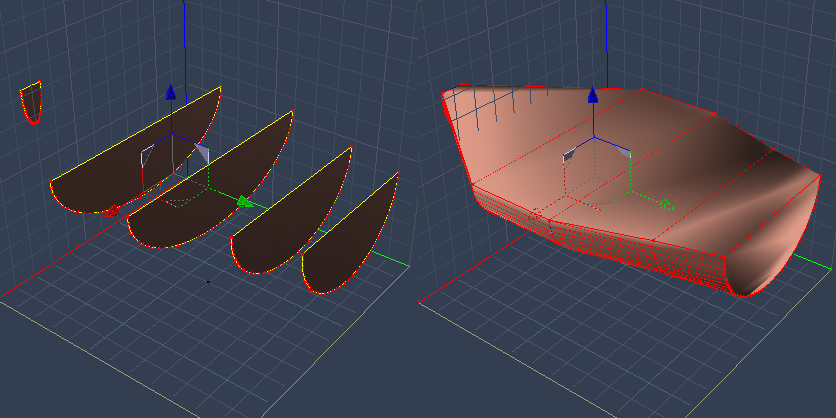
(Image: Cross sections and lofts for a boat)
The same process could be used for the gun barrel that I have used above.
(Image: Cross sections and lofts for the gun image)
The cross sections may be a bit harder to imagine as we have to mentally slice this object into sections which isn’t always easy. Still it is completely feasible and produces results similar to box modeling.
Line Sweeping
Line sweeping (or path sweeping) is similar to both extrusion and lofting in that it uses extrusion and a cross section to create an object along a path of vertices.
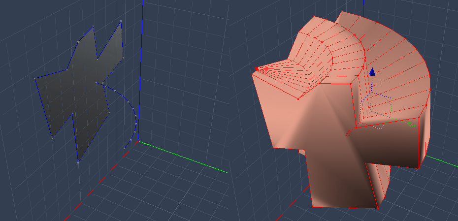
(Image: Line Sweeping a cross section)
This technique allows for more complex curving models and almost organic shapes. If your line curves too sharply, though, you may end up with intersecting facets which would need to be fixed after the sweep.
Lathing
Lathing is the process of rotating an cross section around a central axis point to produce a circular object. Pistons and chess pieces come to mind when thinking of lathed objects.
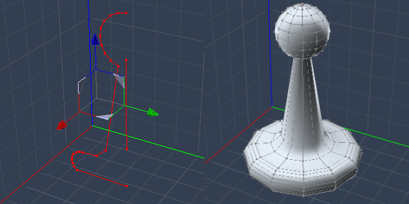
(Image: Cross sections and lathe for the a game piece)
Modeling Concepts
I’m not going to go into too much detail when covering these techniques as they differ from program to program. The concepts are sound as they can apply to many different programs; just by different names. I’ll show you the way, you’ll just need to figure out how it works with what you use.
Edge Manipulation
Edge manipulation refers to a class of modeling that allows you to refine a simple model to a more complex model. By taking edges of the facets you create greater detail by softening hard edges (like the sharp edge of a countertop vs. a beveled edge), and dividing large facets into smaller ones to create details (inset/sunken or relief/raised designs). There are several methods edge manipulation that I use to refine my models.
Edge Extraction
By selecting facet edges, I use the extraction tool to pull a copy of the line down it’s faces, dividing the facets.
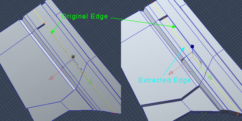
(Image: Single Edge Extraction along faces)
A more complex sub-function of this allows me to extract the edge(s) to both sides of the selection (either removing the selected edge in the process or keeping it) creating a loop of edges around the original selection area.
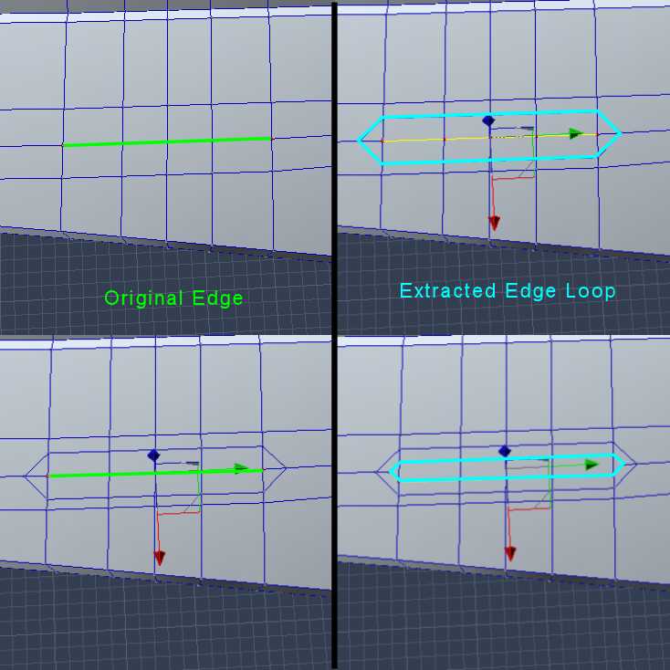
(Image: Edge Loop creation)
These are useful for creating inset or relief designs. Once the new edge/edges is/are in place I can create the detail by extruding the new facet in or out.
Edge Fillet
Hard edges can be softened or rounded by using the Fillet function. Edges are selected and the function applied by choosing how smooth an edge you want and the distance from the edge you wish to go.
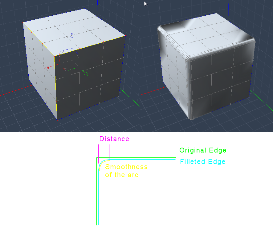
(Image: Filleting edges)
Subdivision
Boolean Operations
Fixing Problems
MeshLab diagnosis
NetFabb (cloud version)

