1

Topic: Hinge (Proof of Concept)

I've been building a hinge set for a Pokeball for the kidlets (who are poke-crazy right now).  I wanted to be able to print almost the whole thing (except for the springs, which I'm cannibalizing broken click pens for).  To make sure that it worked, I needed a proof of concept that I could design the hinge back for the hemispheres.  Doing so took considerable time as I wanted to be able to do this with minimal post process tinkering.

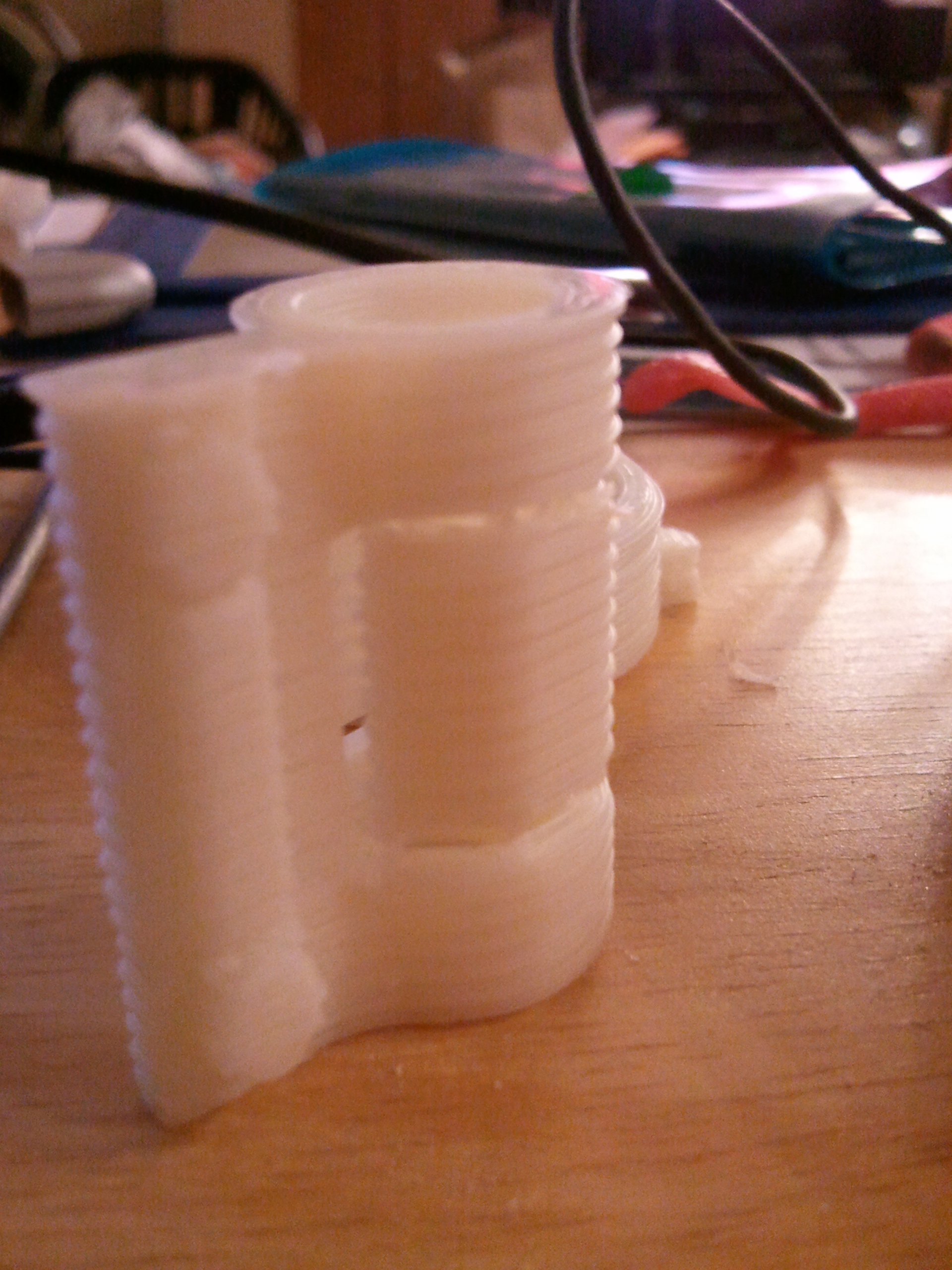
I'm proud to say that I've accomplished this.  I printed the pieces last week and was satisfied with the results.  The hinge moved with minimal effort, but I had to really cut down on the stringing that I was seeing.  I set the pieces up to print along the bed and that made the thing look kind of kludgy and would have require considerable finishing, so I set on a new adventure:  Proof of concept 2:  Vertical placement of the pieces.

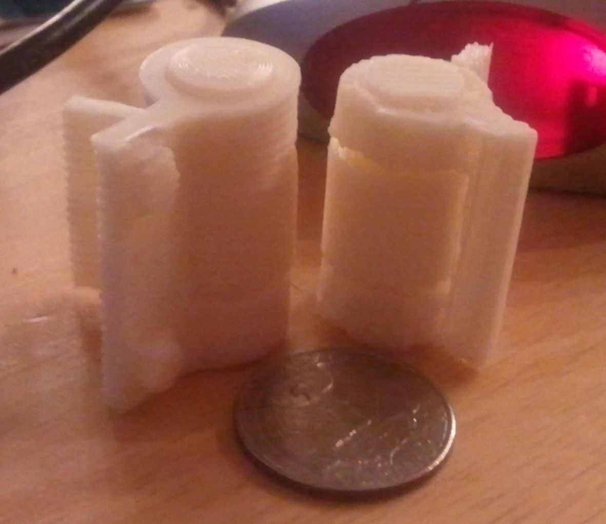
The hinge is 2 part which required that there be 3 hinge points; 2 on the edges and one central.  Add to that the fact that the pieces had posts for mounting on the hemispheres and that adds up to supports.  I didn't like the support structures that were being genereated by either slicer, so following in the footsteps of Lawsy (and his jigsaw replacement), I built my own into the models.  Surprisingly easy once you figured out what could be used.

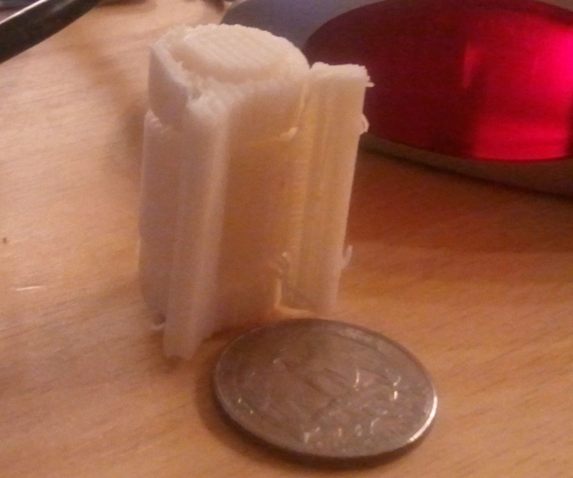
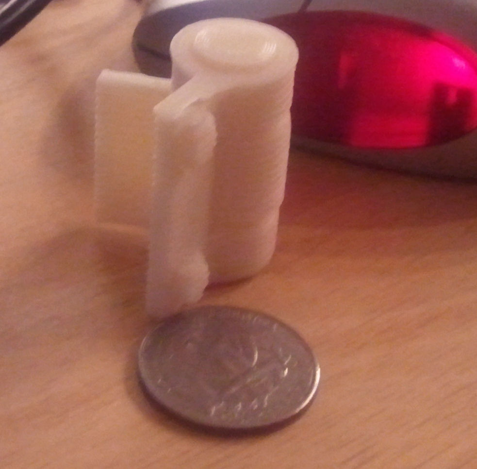
I present the proof of concept in STL.  Should you decide to print this, do it at 100% as this is the correct sizing for the pieces.  Any smaller and you risk throwing the support structures under the bus.  As it is, they snap right off leaving very little to clean up after.  A little filing and the thing should fit together nicely. 

I say "should" since it worked for my machine and I'm still having that dang banding issue on the Z axis, but even with that the parts look pretty clean.  Yes, it is almost 3m of filament at .3mm and a build time of over an hour and a half, but it was SOOO worth the time to see something that came out of my head come to life.

Post's attachments

Hinge.stl 140.51 kb, 62 downloads since 2012-11-28 

You don't have the permssions to download the attachments of this post.

2

Re: Hinge (Proof of Concept)

Nice, do you have pictures of the printed parts you could share

3 (edited by cckens 2012-11-29 20:42:08)

Re: Hinge (Proof of Concept)

Consider it done... at least of the one part that I have a picture of on my phone..
http://www.kenzden.com/download/HingePart.jpg

Parts look good and the hingepin fits the hole and the whole thing works as it should.

One snag.  Printing like this (from a vertical standpoint) is impractical as the support came off easy enough on most, but the strength is not quite what I want as I snapped part of the flange off removing the base of the support (the stuff at the top of the picture near the coupling part).  Central support on the hinge and the stuff in between the couples popped off neat and clean with only a little sanding required to remove the sprues of the support.

I'm working on redesigning the piece for a horizontal layout.  It will require re-working the support so that it's under the flange but that's a minor issue now that I've got the hang of building support structures.

You can see the banding that plagues my prints that I'm now sure is being caused by a bent z-screw.  It's rather evident here.  All other aspects of my printer seem flawless as there isn't any x- and y- shifting.  Just that dang regular banding.

4

Re: Hinge (Proof of Concept)

Yeah, are you the one that put up the video of the z motor doing the mambo?  That was pretty nasty!

5

Re: Hinge (Proof of Concept)

Yep, that was me... I didn't think anything of it when I got it as the micro-moves made by the unit didn't seem to show that shimmy.  Seems like it was that issue.  As I've said, I've calibrated this puppy with every tutorial on this site and other rep-rap sites that might have been the issue.  I finally figured I'd catch it in the act and show the forum what it looks like.  Hope Solidoodle sees it and agrees.

6

Re: Hinge (Proof of Concept)

Here's a few shots of the finished hinges.

This one is the original design.  A little stringy as I turned off retraction for some reason.  This was printed horizonally and at an angle so the I wouldn't need the support
http://www.kenzden.com/download/original-design.jpg

This is the improved design with the support removed;  Printed vertically with modeled supports.  You can see the broken flange on the upper end of the far piece.   Looks better, but not as strong against lateral forces.
http://www.kenzden.com/download/modified-hinge.jpg

Here's the two side by side
http://www.kenzden.com/download/both-hinges.jpg

All were printed at .3 mm as I didn't want to risk .1 until I have .3 printing right.