1

Topic: thrust bearing on new version.

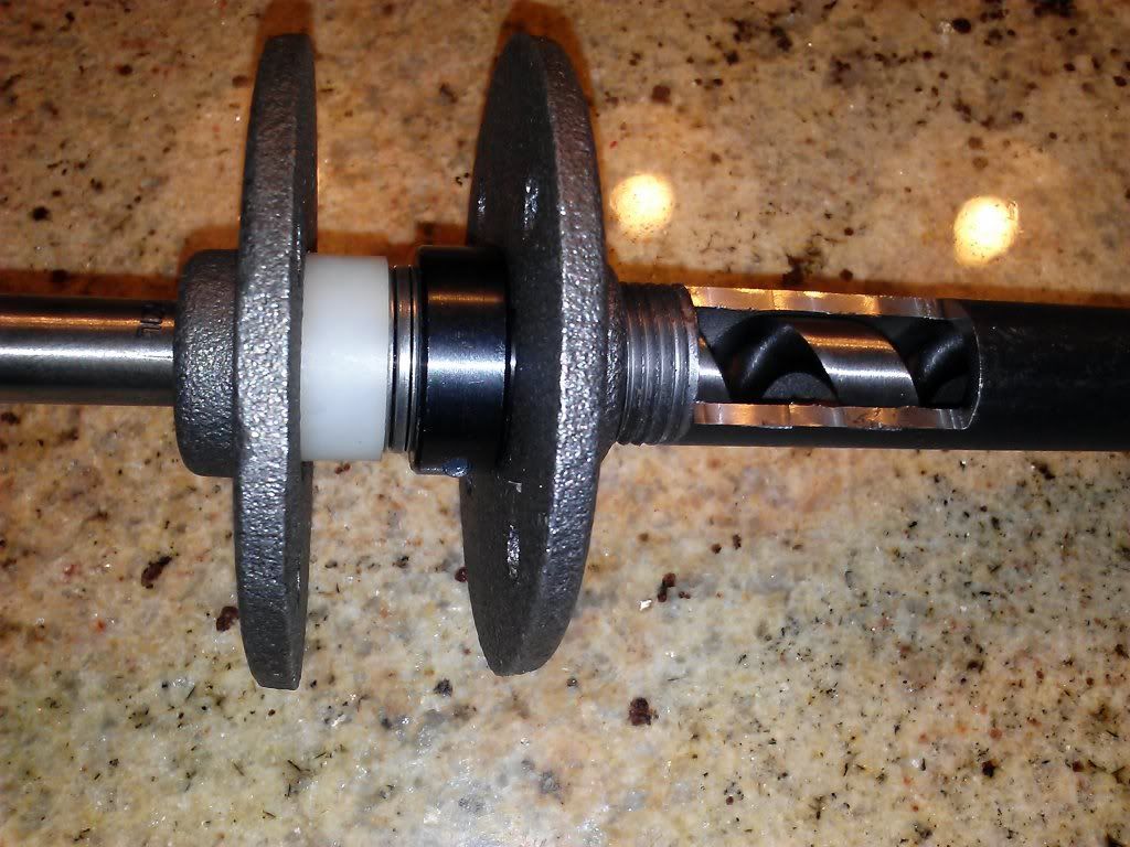
Sorry this may seem very simple to most, but I have no clue how this thrust bearing is supposed to interact withte flanges. I followed all the steps and all I end up with is a nylon bushing, thrust bearing, and collar mashed between two flanges with the collar just grinding up against the flange. Negating any good the bearing would do. The instructions are not to clear to me and the photo is little help. I have gotten to step 7. I feel pretty dumb asking but it is really not obvious to me how this should work.

2

Re: thrust bearing on new version.

Post a photo of what you have. The collar should not grind on anything.I'm betting you don't have the black spacers in place, if they're there then you get 1.25" of space between flanges, which is plenty for the collar, bearing, and bushing.

3

Re: thrust bearing on new version.

http://i183.photobucket.com/albums/x60/curlrup/CAM00866_zps704e4aaf.jpg

4

Re: thrust bearing on new version.

Right. You need the wooden upright and 4 spacers between those two flanges.

If you're following the instructions, yo would not have gotten to what you have without involving the bolts, washers, wooden upright and spacers in what you have above.

5

Re: thrust bearing on new version.

Right I still see no way to make it work even with the wood in there. Do you have a clear pic of how it should go? I also have the enclosure kit. Still can't picture it with those instructions.

6

Re: thrust bearing on new version.

With the enclosure, you add 4 of the included white spacers (1/4") in addition to the 4 black spacers (1/2") which with the two layers of enclosure (1/2") gets you to 1.25".

7

Re: thrust bearing on new version.

Again still don't see how this negates any part of the collar grinding against something. I need a photo.

8 (edited by curlrup 2014-06-19 02:21:38)

Re: thrust bearing on new version.

Let me ask you this. When it is completely together is the auger/bearing assembly riding on the back flange or the tube and front flange? If it rides on the back flange it makes sense. Meaning the bearing compression is coming from attaching the auger bearing assembly to the drive motor and adjusting the rear flange forward via the bolts.

Sorry not trying to frustrate you, I am really not understanding this. Thanks for walking me through this.

9

Re: thrust bearing on new version.

curlrup wrote:

If it rides on the back flange it makes sense.

Back flange.

Pressure from extrusion drives the auger backwards (away from the nozzle). This compresses the thrust bearing against the spacer/back flange. The purpose of the thrust bearing is to carry that thrust load, so that it is not transferred to the motor (which is not rated for thrust loads).

10

Re: thrust bearing on new version.

Ok I get it now. Sorry all of the wording in the instructions mentioned compressing the bearing in the same context as assembling it all with the flanges I was thinking the collar/bearing assembly was compressed between the two flanges. Ok moving on. Thank you.

11

Re: thrust bearing on new version.

It would be really awesome if someone with one of the newer kits made a video of the assembly. ^_^

12

Re: thrust bearing on new version.

Tomek wrote:

It would be really awesome if someone with one of the newer kits made a video of the assembly. ^_^

I second this motion.

This is a crowd funding thing that I'm running: http://www.gofundme.com/bvi140 It's for pretty selfish reasons tongue

13

Re: thrust bearing on new version.

I'm struggling with this too.  Is this image correct?  With this configuration, there is no compression on the thrust bearing, and the auger can move axially within the barrel a few centimeters.  Also, the nuts reach the end of the threads on the bolts, resulting in a bit of looseness of the whole assembly.  Should I be using the slightly thicker wood spacers from the enclosure kit instead?

Post's attachments

20140624_124128.jpg
20140624_124128.jpg 2.66 mb, file has never been downloaded. 

You don't have the permssions to download the attachments of this post.

14

Re: thrust bearing on new version.

Correct. The compression comes from the melted plastic during extrusion. Its in the instructions, step 6.

THE INSTRUCTIONS wrote:

Axial movement of 2-3cm is normal. Slide the auger so that the thrust bearing is compressed during the future assembly steps. Pressurized plastic will handle the compression in operation.

I don't know how else to draw attention to this. Red color? Size 72 font?

Sure, you can use the laser cut spacers instead. There's a variety provided to compensate for manufacturing tolerances.

15 (edited by smithwoosley 2014-06-24 17:17:24)

Re: thrust bearing on new version.

Yep, just checking.  The mention of compression of the bearing is what threw me off.  Thanks for clearing it up.

Also (I assume since it is in bold in the same step in the instructions) that I will need to thread the barrel in further so the feed screw protrudes?

16

Re: thrust bearing on new version.

Thread the barrel in as tight as you can, be sure to only apply force on the short end of the cutout (towards the flange).

For some folks this is more than others, so if you need to fudge the 95mm measurement a bit to get the tip of the auger poking out, go ahead. The 95mm is just a ballpark, the tip sticking out of the auger is what matters.

17

Re: thrust bearing on new version.

And this is with the auger pulled back away from the nozzle end of the barrel, with the bearing in compression?

18

Re: thrust bearing on new version.

Mhmmmmm.