1

Topic: Different PH heater connector

I have a Da Vinci 1.0 that I got cheap. I've been modifying it. I found a replacement Da Vinci print head on ebay and bought it.
It came with replacement wiring, but its has a 7 pin connector on the print head, whereas mine is 6 pins. The other end of the wires is 6 pins, so that interfaces with my board. The heater wire has a different connector on it also. White conector, my original print head has smaller black connector. The new one came with wires (white mating connector) to run to the motherboard.
http://soliforum.com/i/?LZpJkpX.jpg

1. What da vinci does this fit?
2. is this just the new version?
3. I'll have to run both sets of wires to the print head to be able to swap print heads (one for ABS with original fan, and one for PLA with extra fan and soda can heat sink add ons).
http://soliforum.com/i/?zYZcLZ8.jpg

Dan
FFCP
Da Vinci 1.0 - Repetier 0.92!

2

Re: Different PH heater connector

This reply is a little late but,

Answering 1 and 2: It is a newer variant print-head meant to be used with DaVinci 1.0A's (or very late 1.0's) which have a newer revision motherboard.
(For quick reference, the older motherboards had tiny little "stepstick" styled stepper drivers. The newer motherboards don't and sometimes are the color blue.)

3 Doesn't seem to be a question?

Are you actually asking how to connect the newer print-head pcb (7 pin) to your older styled (6 pin) motherboard? Or did the ebay seller already give you wiring for this?
I do have some connector pinout diagrams/images for both boards that I made a while back ago that may help. I'll post them in a few.

---

The white heater connector is a JST "HIL" series connector.
It's specific model number is HILP-02V-1-S and it mates with a HILR-02VF-1-S (female)
There's something kinda important here, these JST HIL connectors are rated for 5 amps max.

The older black connector was a JST "SM" series connector which are pretty common and you can get a box of them off amazon, etc.
Note the SM connectors are only rated for 3 amps max.

In which case it appears the older print-heads/hotends might use 30W heaters (draws 2.5A) while the newer 1.0A hotends use 40W heaters (draws 3.33A) and they changed their connectors to reflect this. (Therefore your new hotend is probably 40W.)

Anyway, if the seller didn't give you the female-to-board wiring for it; you'd want to change the connector right? so i'd suggest not getting any JST HIL connectors since they might require a special expensive crimp tool.

I can't reeeally recommend using a JST SM connector over it's rated maximum current either, even if it is by a small amount.
A good replacement connector could be a Molex Micro-Fit connector (rated for 8A), or a Mini-Fit Jr connector (rated for 16A), or even spade quick terminals; whatever. Just better than 3.333A if you want to be safe in the long run.

3

Re: Different PH heater connector

Ah, I just saw your other posts with your mods so far, cool!

So for the most part, the older style extruder pcb is already well plotted out by a blogger going under the name "SteelCity" , and you can see the schematic he made here: https://steelcityelectronics.com/da-vin … ruder-pcb/

Here's a pinout I've made of the older style motherboard's "Fan" connector the extruder pcb connects to, for reference:
(I've quickly added a header for these images to make it clearer which board they belong to.)
http://soliforum.com/i/?skev1fl.jpg

The text in gray lists the peripherals and the pin number of the microcontroller for firmware changes etc; albeit there's some components in-between the IC pins and the connector obviously (resistors etc).

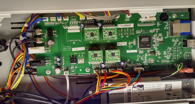
And for the 1.0A boards:
http://soliforum.com/i/?z1FSjE8.jpg

Yeah, the only real difference is the extra fan pin that was added.
It's for the unpopulated "fan b" port on the extruder PCB.
Looks like they were probably going to add in a layer cooling fan of sorts, but for whatever reason decided not to in the end. Oh well.

To help you match the pins to the new extruder, here's a quick copy paste of the pinout text applied directly to a picture of the 1.0A extruder PCB:
http://soliforum.com/i/?iExT9fr.jpg

All you need to do is remove the pin and wire of "Fan B" from the replacement wiring connector on one end.
On the other end you'll need a 6 pin JST-PH connector housing. If you have one, you can rearrange the pins:

If you look closely at the wiring connectors you'll see tiny little plastic tabs you can slide a tweezer under -> gently lift up -> and pull out the pin/wire. (Don't do they too many times as they'll get weaker and eventually fail.)
Then you can insert the pin/wire into another slot.

Or just any way to connect the wiring to the board I guess.


Side note:

I'd really recommend getting a JST-PH assortment pack such as this: https://smile.amazon.com/Pieces-JST-PHR … YP4T9?th=1

and a crimping tool such as: https://smile.amazon.com/IWISS-IWS-3220 … B078WPT5M1

Especially if you're going to work with the board often, or even other electronics to be honest.
JST-PH connectors are literally almost everywhere.


Hope this helps!