1

Topic: Da Vinci 1.0 modifications and better instructions -moved

I'm moving this from the XYZ folder to the Xyz Printing hacks & Mods folder. Where I should have put it initially. And adding photos like I said I would.

I got hold of a cheap Da Vinci 1.0 which needed a little work before it would print. Fixed the jammed up dirty print head, and a few other things and got the slightly damaged bed reasonably level and I was able to print. Not bad for a few $20's.
I have another printer (FFCP) and have been printing for a few years so I know about upgrades and improvements, which I started looking at for this printer.
The most obvious thing is the printer cartridge. And the very limited slicer program.
I could see this needed was a cable chain for the print head cables which tend to droop down behind the print head behind the print head when it homes.
And the filament feed path, which isn't really controlled very well.

After looking around I found the Repetier 0.92 firmware upgrade, and a bunch of parts to upgrade on Thingiverse, and TBD's bed upgrade post .

I thought I'd document what i did so others can improve their printers also. Specifically better instructions for the firmware upgrade. Those instructions are pretty thin unless you have lots of experience with Arduino, which I didn't. I struggled a lot with a few steps of the upgrade, but ultimately figured it out. Awesome thanks to Luc and everyone else who made that possible

So I'll make a couple posts each one will be an upgrade.

Dan
FFCP
Da Vinci 1.0 - Repetier 0.92!

2

Re: Da Vinci 1.0 modifications and better instructions -moved

The 1st easiest upgrade I did, which may or may not help with the printing was to replace the short pieces of filament tubing with one long piece. This takes the pull load off of the filament when the print head moves forward and seems to help a little with print quality. I have a lot of that tubing around (like 10') because I needed some for another printer I worked on.

So I pulled out the short (~2") sections of teflon tubing from the print head and from the rear frame feed through with some pliers. Then I cut a long (23") piece of standard teflon feed tubing and fed it into the print head and the rear nipple. I used a longer piece  because I did this as part of the upgrade to Repetier and mounting a standard 1 kg reel on the back of the Da vinci 1.0, so I wanted it to stick out the back of the printer by an inch or so. Get 24" and cut it down as you feel after you try it out a bit. Its OK if there is excess in the printer main area, it just coils up under the top and follows the print head around.

To get it in, you just push it down into the print head slowly and forcefully and watch to see that it goes through the lower feed funnel in the print head. You do the same for the rear feed through nipple. Loading filament is a little more trouble than normal, you have to push it into the tubing back at the reel area a little at a time. But it works and the filament goes right into the print drive without a problem.

update: I find that loading filament is easier if I pull out the teflon tube, slowly and steadily. Then get the filament loaded, by using the unloading lever for the pinch roller and getting the filament down into the hot break tube. Then I can push the teflon tubing back into place.

Post's attachments

20200219_213044[1].jpg
20200219_213044[1].jpg 3.57 mb, 1 downloads since 2020-02-20 

You don't have the permssions to download the attachments of this post.
Dan
FFCP
Da Vinci 1.0 - Repetier 0.92!

3

Re: Da Vinci 1.0 modifications and better instructions -moved

The Repetier Firmware upgrade needs more detailed instructions for us Arduino noobs. So here is what I documented in my several attempts to get it to work, which I did after a couple evenings of digging around and failed uploads.

This is all based on the latest version of the Git Hub upgrade posting by Luc.

1. Down load the Repetier 0.92 update files from:
https://github.com/luc-github/Repetier- … -4-Davinci

Extract those files to a folder you make in your Documents folder on your C: drive. Or any folder location you can remember. You will use those files for the update, and any time you need to reflash your Da Vinci.

Download Arduino 1.8.0 from https://www.arduino.cc/en/Main/Software
You have to click on the link for older software which gets you to:
https://www.arduino.cc/en/Main/OldSoftw … s#previous

Then download 1.8.0 to your computer and it will be an .exe file. Click on that executable file and install to your Program Files folder.

Download Repeiter Host from https://www.repetier.com/
unpack and install that . It automatically includes Slic3r. So you don’t need to separately download Slic3r. I found out that a separate installation of Slic3r will cause Repetier Host to fail. So just let Repetier Host use the automatic download version.

You can Run Arduino 1.8.0 at this time, but the compiling and upload to your Da Vinci won't work, so you need to fix that by using two different files to get it to see your Da Vinci mother board. So modify your Arduino program with the following modifications

NOTE: note "Dano" is my user name on my computer. So on your computer you should see your user name in your C:\Users\.... folder.

Copy and paste the file "variants.cpp" from:

C:\Users\Dano\Downloads\Repetier-Firmware-4-Davinci-master\Repetier-Firmware-4-Davinci-master\src\ArduinoDUE\AdditionalArduinoFiles\Arduino - 1.8.0 -Due 1.6.8\Arduino15\packages\arduino\hardware\sam\1.6.8\variants\arduino_due_x

To: C:\Users\Dano\AppData\Local\Arduino15\packages\arduino\hardware\sam\1.6.12\variants\arduino_due_x
Windows will ask you if you want to replace the file, and you click yes.

NOTE: App Data is a hidden file with program settings files in it. If you don’t see it, go to your User folder in Windows Explorer. At the top, select the View Tab, then check the box for hidden items. You should then see AppData folder

OK now start Arduino 1.8.0 . You might notice that the icon has changed to a generic blank icon, not a problem.

In the Arduino menu tabs, select Tools, then Boards "arduino somethingorother". Scroll down until you see the “Arduino Native USB" type board, which should be all the away at the bottom. If that is not selectable (not there), scroll up and select “Board Manager” at the very top of the list of boards. You'll get a new window, which paragraphs of board listings. You have to read the listings and find the type that supports "Arduino DUE". Click on it, and an Install button should show up on the right lower edge of that paragraph.  Install that (85 kB or so). Then close that window and get back to Boards (Tools-Boards). You should then be able to select Arduino Native USB down near the bottom of the list. This is the same change that is accomplished by moving the USBCore.cpp file (I think, since I didn't go that route).

Now in Arduino 1.8.0, open the  Repetier.ino  file which is found in
C:\Users\Dano\Downloads\Repetier-Firmware-4-Davinci-master\Repetier-Firmware-4-Davinci-master\src\ArduinoDUE\Repetier
Click on the Configuration.h tab. You will see a big long set of code.

Right near the top, in the first block of ******Edit these Settings*****
Set the first line to the right number to match your machine. 1 for a davinci 1, for a a 2 with one fan, etc…. Just like it says in the comments //........
Second line is so that the firmware matches the board version, so get the right board version (this can be determined by what jumper pins you short to clearout the old firmware, J1 is the 1st version boards, and I think its J37 for the 2nd generation boards. (Look around in the upgrade postings for more info on board version).
Third line is modified if you add a filament cooling fan and wire your original fan to a 5vdc power source from the board so it is on all the time. (that's another mod to do).
#define DAVINCI 1// "0" if not DAVINCI, "1" For DAVINCI 1.0, "2" For DAVINCI 2.0 with 1 FAN, "3" For DAVINCI 2.0 with 2 FAN, 4 for AiO (WITH NO SCANNER SUPPORT)
#define MODEL  0//"0" for first generation (jumper JP1 to reset ) , "1" for new generation   (jumper J37 to reset)
#define REPURPOSE_FAN_TO_COOL_EXTRUSIONS 1 //Setting this to 1 will repurpose the main Extruder cooling fan to be controlled VIA M106/M107
                                           //Warning: for DaVinci 1.0 need to add a permanent fan with power supply to cool extruder
NOTE: if you don't have a new plastic cooling fan right now, just leave REPURPOSE_FAN_TO_COOL_EXTRUSIONS 0, set to zero. You can always re-open Arduino in the future, change that after you have upgraded the fans, recomplie and re-flash your motherboard. You'll do something similar for the heated bed.

NEXT: if DON't upgrade the heated bed, You don't have to change the thermistor settings. So you can skip this next section and get to compiling and uploading.

If you change out the heated bed as I did AND use the thermistor in the heated bed, you need to make these changes (read the heated bed post below).

Scroll down to the 2nextruder section and look for the thermistor definition listings:
// What type of sensor is used?
// 1 is 100k thermistor (Epcos B57560G0107F000 - RepRap-Fab.org and many other)
// 2 is 200k thermistor
// 3 is mendel-parts thermistor (EPCOS G550)
// 4 is 10k thermistor
// 8 is ATC Semitec 104GT-2
// 13 is PT100 for E3D/Ultimaker
// 5 is userdefined thermistor table 0
// 6 is userdefined thermistor table 1
// 7 is userdefined thermistor table 2
// 12 is 100k RS thermistor 198-961
// 13 is PT100 for E3D/Ultimaker
// 14 is 100K NTC 3950
// 50 is userdefined thermistor table 0 for PTC thermistors
// 51 is userdefined thermistor table 0 for PTC thermistors
// 52 is userdefined thermistor table 0 for PTC thermistors
// 60 is AD8494, AD8495, AD8496 or AD8497 (5mV/degC and 1/4 the price of AD595 but only MSOT_08 package)
// 61 is AD8494, AD8495, AD8496 or AD8497 (5mV/degC and 1.25 Vref offset like Adafruit breakout)
// 97 Generic thermistor table 1
// 98 Generic thermistor table 2
// 99 Generic thermistor table 3
// 100 is AD595
// 101 is MAX6675
// 102 is MAX31855

Pick the Type # you will use.
Then Scroll down to the Heated Bed Section and look for:

// Select type of your heated bed. It's the same as for EXT0_TEMPSENSOR_TYPE
// set to 0 if you don't have a heated bed
#define HEATED_BED_SENSOR_TYPE 6
I used sensor type 4, its 10K and it worked (more on that in the heated bed upgrade post). So my line reads:
#define HEATED_BED_SENSOR_TYPE 4

OK, now you are ready to Verify and compile and upload.
In Arduino 1.8.0 check the COM port under tools to see that you have the right port to match where your Da Vinci is connected. if you don't the Upload will fail (and you can choose another port and try again, so not fatal).

Select the Check Mark button in the Arduino menu bar to “verify” the sketch (program). If that works, then you are ready to flash the Da Vinci.

Clear the old Da vinci firmware and ready the board for the new upload by shorting the two pin holes at J1 (or J37) and turning on the power for 5 seconds. I used a metal tweezers, some used their needle nose pliers, or a piece of wire. Turn the printer OFF, then turn ON again and you should see 2 black bars in the LCD screen of the Da Vinci. Good your Da Vinci is wiped.

Back to Arduino, click on the Right Arrow button to Upload the compiled sketch to your Da Vinci. After a bit the Da Vinci should beep and the LCD screen reset with..... the extruder temp 22 / 0 and bed temp 23 /0 on the 1st line, z position on the second line, and Mul:100%Buf: 0 on the third line. If that fails, check the COM ports to see you are on the right one to the printer.

I found that if I failed the upload, sometimes the computer would fail to see the printer. If I re-did the J1 short On/off/on, the computer would again see the printer and I could try another upload.

o  if you got a good upload, then press the OK button on your Da Vinci and scroll down to Settings, select it.  Scroll down to Store > EEPROM  and push the OK button to store, then use the home button to get back to the top screen.
And you are good.

Next start Repetier Host and connect it to the printer. On to the next post.

Dan
FFCP
Da Vinci 1.0 - Repetier 0.92!

4

Re: Da Vinci 1.0 modifications and better instructions -moved

Once I got the firmware flashed with Repetier 0.92 and Repetier Host running on my computer I tried to print. Which failed. The print head kept moving up to the left front and jamming in the corner. Its a problem with the definitions of the bed area, and what the printer vs Slic3r thinks is home (0,0).

That is covered here: http://www.soliforum.com/topic/18410/pr … 2-upgrade/

Dan
FFCP
Da Vinci 1.0 - Repetier 0.92!
5

Re: Da Vinci 1.0 modifications and better instructions -moved

Heater bed upgrade.
I saw a post here on Soliforum about a heater bed upgrade to a Mk3 aluminum bed. Cool! (i'll edit with that posting link after I find it again).  I use 1/4" glass plates on my Flashforge CP and those work great.  I can swap the plate after I finish printing with a hot pad to grab the plate and set it aside. When the print and the plate cool the difference in CTE causes the prints to pop off by themselves. And I can print again on the other (2nd) plate. SO I want to do that also.

I bought this Prusa Aluminum bed frame:
https://www.amazon.com/gp/product/B07RK … &psc=1

This 220 mm x 220 mm MK3 Aluminum Heated bed with wires (built in thermistor):
https://www.amazon.com/gp/product/B07JL … &psc=1

And a 220mm x 220mm borosilicate glass plate. Thought I bought a square one, but I inadvertently order one with clipped corners. it still works.

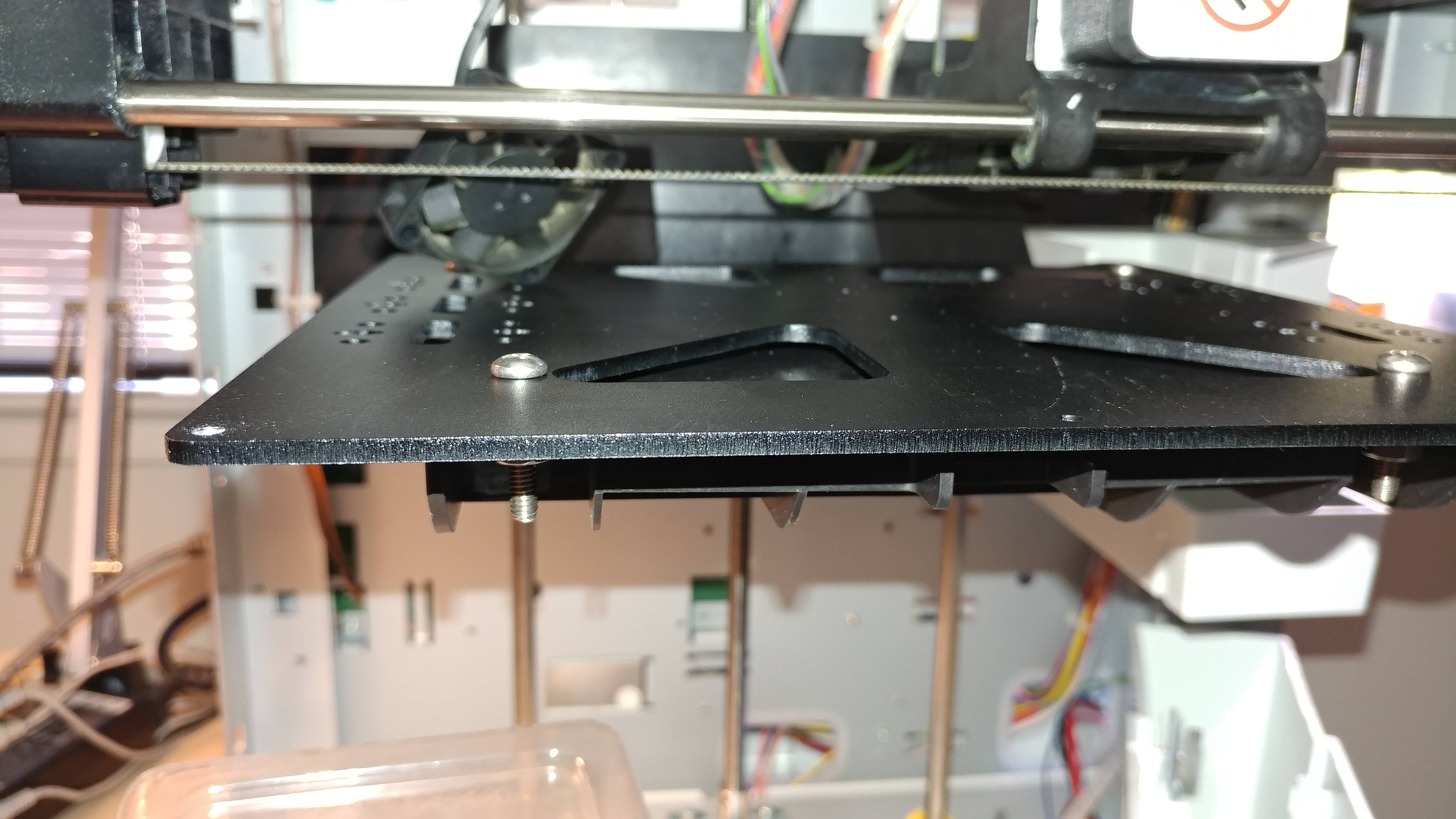
I used 4 #8-32 Pan Head screws with nuts and star lock washers (because I got then for $0.05/0.02 each at a closeout electronics hobby shop place) to hold the Prusa plate to the Da Vinci Z carriage. They need to be at least 5/8" long, so get 3/4. You could also use M6x1.0 x 20mm screws, nuts, washers.

You also need 4 #6-32 flat head phillips screws, about 1" long. 8 nuts.
2 ~1.5 inch springs from the spring bins at Ace Hardware. Cut in half to yield 4 springs, one for each corner of the heated bed.

How to:
1st I used a countersink bit in my hand drill and on the plain aluminum side of the heated bed, and countersink drilled the 4 corner holes so that the Flat top #4 screws (or M3 Flat top screws) are just below the surface of the aluminum plate. DON'T countersink too much or you'll be buying a new heated bed. If you have a clipped corner glass plate you don't need to countersink the screw heads.

You have to removed the whole Z ahttp://soliforum.com/i/?NjppXUK.jpgxis set up from the printer, so this is a good time to upgrade the Z rod mounts with these from Thingiverse. And the Z screw guide.
https://www.thingiverse.com/thing:455674
https://www.thingiverse.com/thing:1051409

1. Undo the 2 set screws that hold the Z screw rod to the aluminum motor coupling. Then the Z screw will slide up. Don't removed the motor or the aluminum coupler.
2. Undo the wiring from the motherboard to the heated bed. That's the 2 larger black wires and the small red/blue (?) wire to the thermistor.
3. Undo the lower Z rod mounts (4 screws).
4. Undo the upper Z rod mounts (4 screws).
5. take the right z rod out, then the whole carriage comes out. Carefully.

6. Take z rods and z screw out ot the Z carriage, and remove the old bed. Set aside.
7. Drill out the REAR 2 old bed adjustment screw holes to allow for the M6 or #8 screws. Do the same with the front 2 (TWO!) bosses at the right and left edges of the z carriage. The front two are not previously drilled.

8. Then locate the Prusa plate in the center (left to right) and located it so that the new Mk3 bed will be in the same place (front to back). Plate cut out to the rear for the wiring harness. Clamp the plate to the Z carriage so it won't move, or have a helper hold it in the right place. With the Z carriage upside down, drill through the holes in the z carriage that you made in #7 and through the Prusa plate (PRUSA PLATE!).
9. Bolt the Prusa plate directly to the plastic Z carriage with the 4 -#8  (or M6 ) screws and nuts/washers (see my attached picture.
10. Test fit the Mk3 bed with the wires attached and see how the wires run. Drill a couple 3/16" holes in the plastic of the Z carriage so you can put in a couple tie wraps to hold the wiring harness to the Z carriage. (you won't see that in my pictures as I did that later). REUSE the spiral wrap on the new wiring harness.

11. Take the Mk3 bed off and then install the Z threaded rod and left slide rod to the Z carriage. Fit the upper and lower Z rod mounts to the left and right Z slide rods.
12. Put the Z carriage back into the printer, putting in the right Z rod second, and screwing in the 8 screw which hold the Z rod ends in place. Put in the upper Z Screw support now too. Make sure you orient the clamp screws on the upgraded Z rod ends so you can loosen or tighten them after the whole z carriage is installed.
13. Install the Mk3 bed (with wiring) to the Prusa plate with screws and springs and nuts. Then tie wrap the harness to the Z carriage and route the wires back to the mother board.
14. The main power wires get put back on the bigger screw terminals and excess wire coiled up and tie wrapped. The thermistor wires have metal female ends on them, which do not fit into the old connector body, I just put a thin layer of electrical tape over those and slid them on the pins of the thermistor connector on the mother board. I might update this if I can find the right connector to buy online (electronics supply store?).

Power up your Da Vinci and you should see that the extruder temp 22 / 0 (measured temp / set temp) and the heated bed temp 23 / 0 are nearly the same as your room temp (22C). If the bed temp is way off, you need to update the thermistor TYPE in the repetier 0.92 (in arduino compiler) firmware and re-flash / upload (see my previous post on Repetier 0.92 above).  I used type 4 and it was a 1 degree difference from the extruder temp. If it says DEF / 0 or something else, recheck the pin connections and make sure they are not touching each other.

Post's attachments

Prusa plate bolt.jpg
Prusa plate bolt.jpg 915.49 kb, file has never been downloaded. 

Prusa plate bolted.jpg
Prusa plate bolted.jpg 1.14 mb, file has never been downloaded. 

Prusa plate test fit.jpg
Prusa plate test fit.jpg 1.6 mb, file has never been downloaded. 

You don't have the permssions to download the attachments of this post.
Dan
FFCP
Da Vinci 1.0 - Repetier 0.92!
6

Re: Da Vinci 1.0 modifications and better instructions -moved

I'm still working on the fan modifications but some details now and I'll update later with more.

I found the fan mods for the DA Vinci printers on Thingiverse and looked at a bunch. I printed this one to start with
https://www.thingiverse.com/thing:1830306

It uses the original fan and just makes it more efficient.
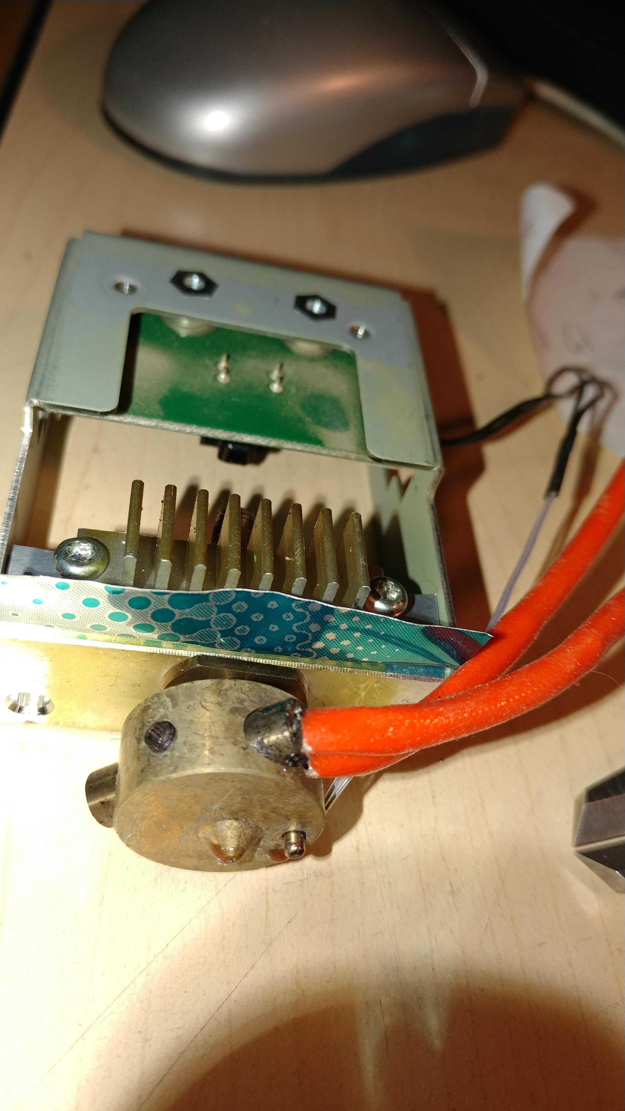
My hack to that was to use a bit of soda can aluminum under the heatsink, and bent 90 degrees to deflect the fan air from the print bed. http://soliforum.com/i/?ituAD5g.jpg

I also printed the front clip on 50mm fan mount  to cool the print. its a weird size and if you looked the pictures on THingiverse, it looks like its glued in place. So I made an adapter plate, a simple flat plate, that I glued onto the fan and then I can screw on a standard 50mm fan (39.6mm hole spacing).
https://www.thingiverse.com/thing:4163969
https://www.thingiverse.com/thing:824926
I wired that 50mm fan to the fan connector on the print head, so its controled by the software. Not super happy with this, I might make or print a different one. It drags on the small binder clips that I have holding down the glass plate to the bed.

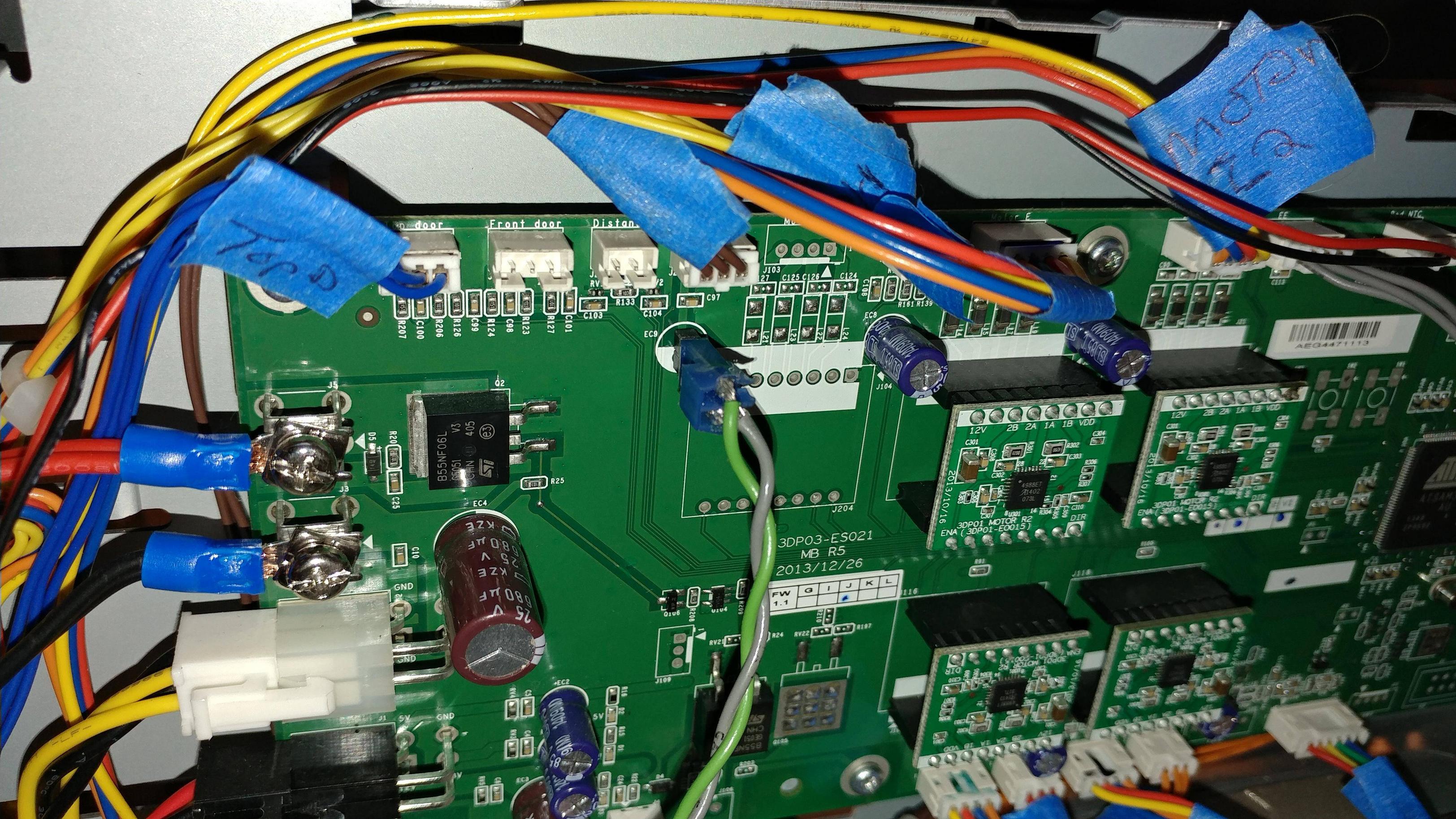
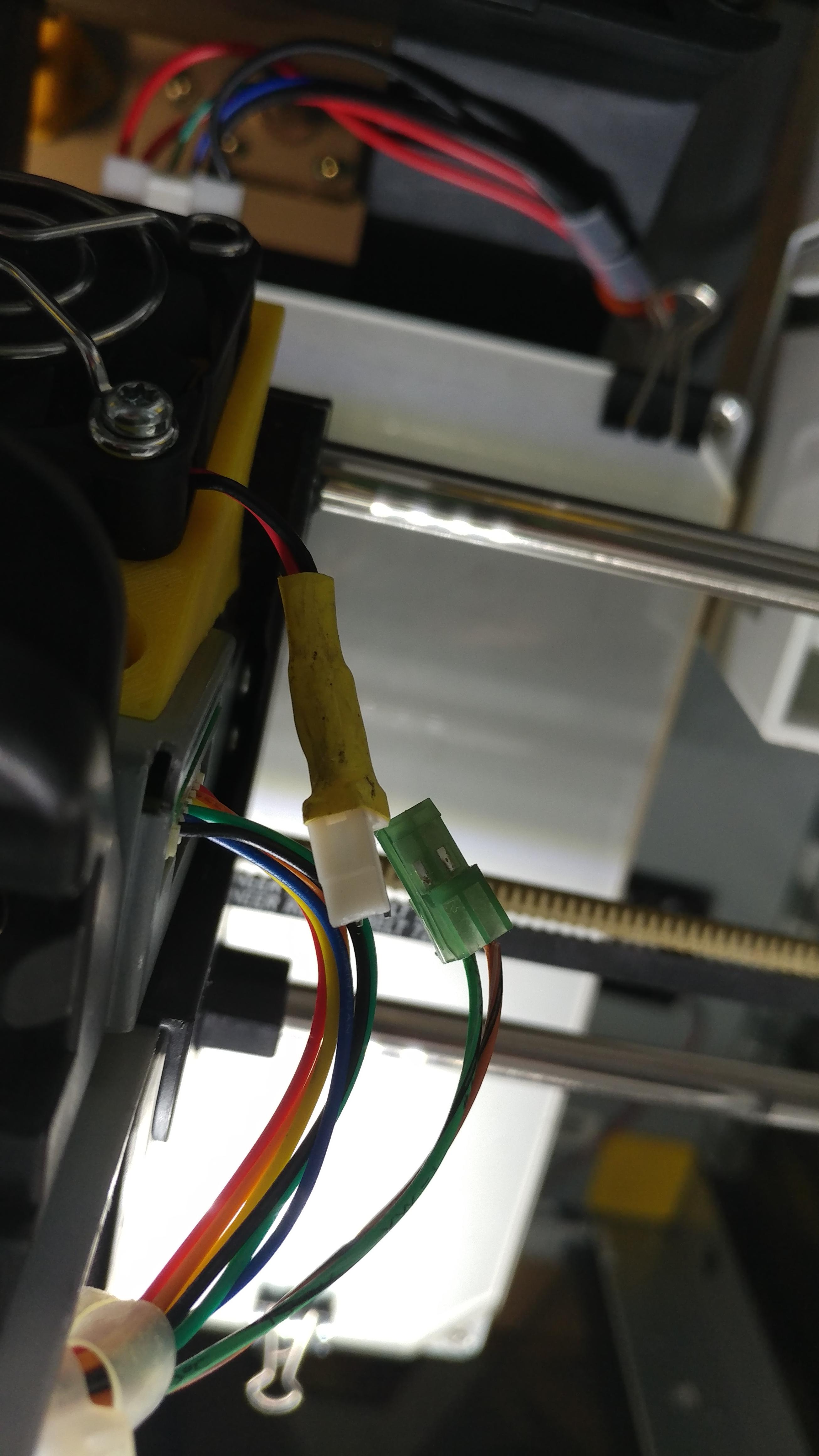
Wiring. I got a 2 pin board mount and mating connector to power the original fan from the mother board, then I would use the original wiring and connector to power my new print cooling fan.

Pulled out the motherboard and found a +12vdc and ground location (see photo). Soldered in the 2 pin board connector and ran wiring directly to the original 40mm fan.
http://soliforum.com/i/?5S3fJol.jpg

WHOA! its strong. Yeah, the original fan is a +5 vdc 1.18W (.24A) fan, and when you run it on +12vdc it really moves a lot of air. (thus the soda can deflector). It cools too much for the print head, so I need to dial that back (with PWM adjustable circuit) or find a +5 vdc pin to run it off of the motherboard and move my 2 pin board connector.
PWM fan controler circuits here (for +12 vdc)
https://www.circuitspedia.com/12v-dc-mo … -with-555/
I ended up finding a 5v and ground on a 3 pin connector set of holes in the motherboard (you can see it in my photo if you follow the wires down about 1 inch, 3 holes with a triangle pointed at the top hole). I soldered in two 6" wires and put a 2 pin connector on the end of that, then mating connector and long wires out to the print head, with another connector that matches the one on my original fan. http://soliforum.com/i/?vEhnK7C.jpg

I found the JST connectors (M&F) and short wires on Amazon, 10 packs for $8.5. I should have used these, but just found them. Maybe I'll re solder the new connectors in when I get the parts. JST connectors are the 2 pin type used for the thermistor and fan that plug into the print head board.
https://www.amazon.com/Upgraded-Connect … X48EP854JQ

Dan
FFCP
Da Vinci 1.0 - Repetier 0.92!