Topic: Thermocouple with Rumba and Marlin - SOLVED
Hi
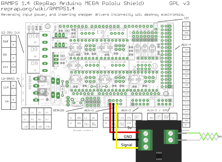
I'm trying to get this: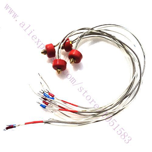
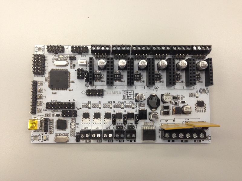
To work with a rumba board and Marlin firmware
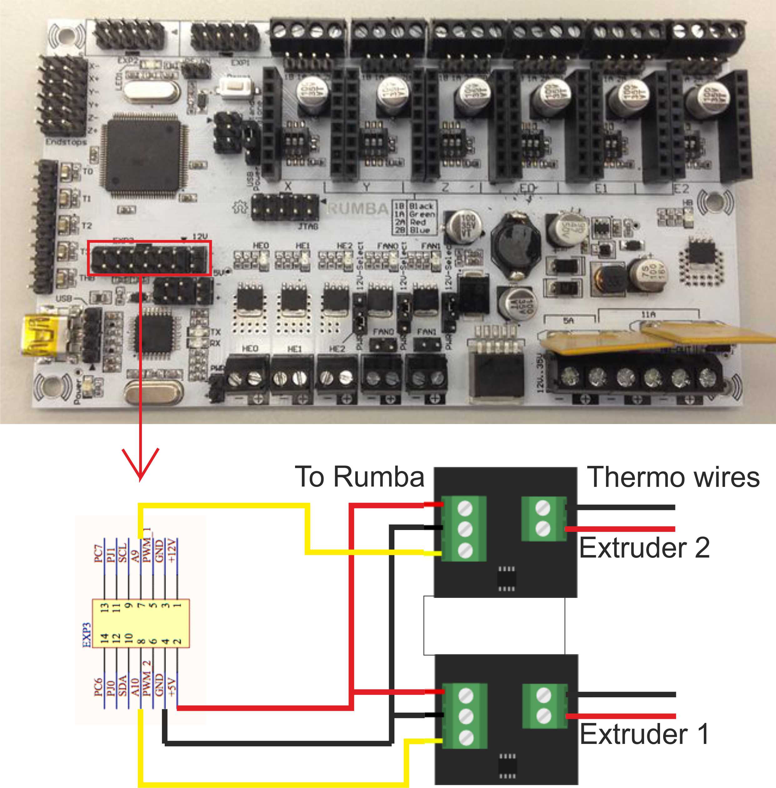
After several searches made the conections as follow: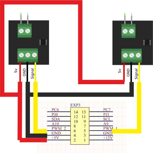
In marlin set:
#define TEMP_SENSOR_0 -1
#define TEMP_SENSOR_1 -1
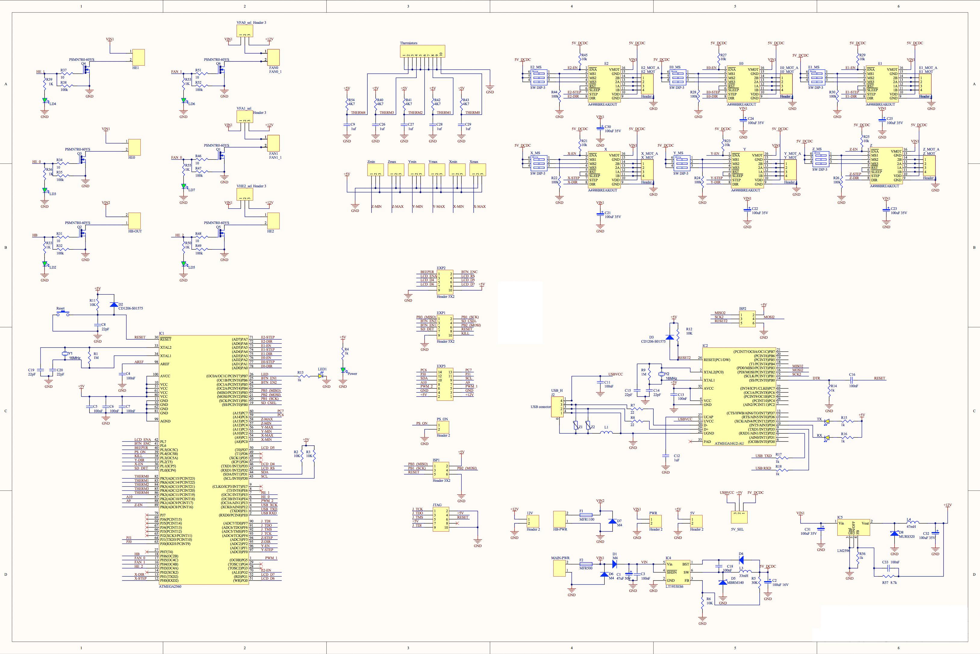
Pins used
+5v pin 2
Ground pin 4
Signal 1 pin 6
Signal 2 pin 5
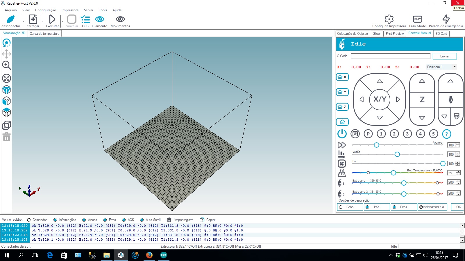
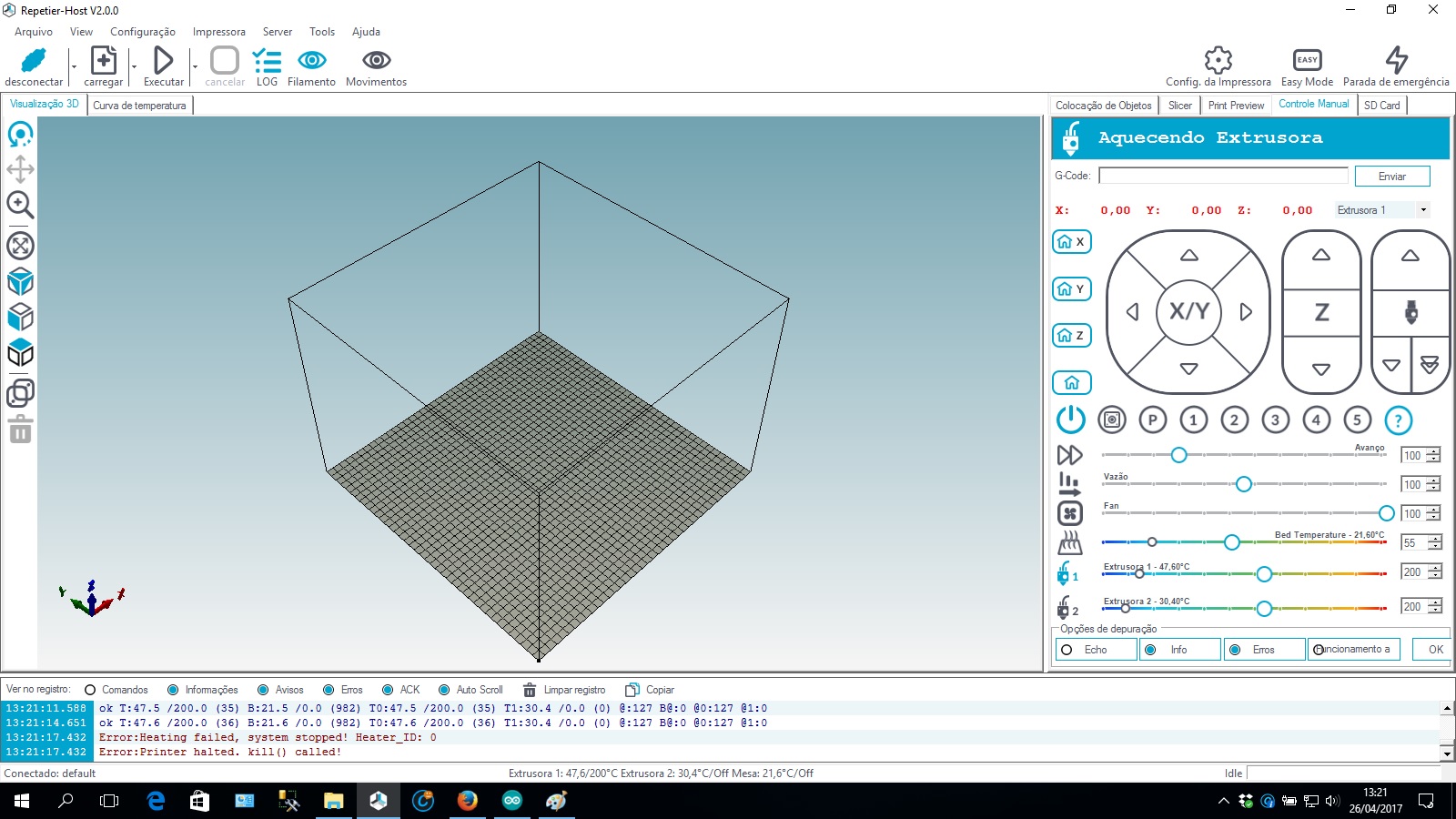
First time i tried i got 300º for extruder 1 and 2
Changed in config_adv
#define TEMP_SENSOR_AD595_GAIN 0.1
tried and it reads 30º for both, but if i turn on any heater i don't get any changes on temperature.
Can someone help me on that.
I tried searching, but i can't find much information on this theme