<?xml version="1.0" encoding="utf-8"?>
<feed xmlns="http://www.w3.org/2005/Atom">
	<title type="html"><![CDATA[SoliForum - 3D Printing Community — Connections between Hardware Components: Need Help !!!]]></title>
	<link rel="self" href="https://www.soliforum.com/feed/atom/topic/17778/" />
	<updated>2018-12-12T15:26:17Z</updated>
	<generator>PunBB</generator>
	<id>https://www.soliforum.com/topic/17778/connections-between-hardware-components-need-help/</id>
		<entry>
			<title type="html"><![CDATA[Re: Connections between Hardware Components: Need Help !!!]]></title>
			<link rel="alternate" href="https://www.soliforum.com/post/147880/#p147880" />
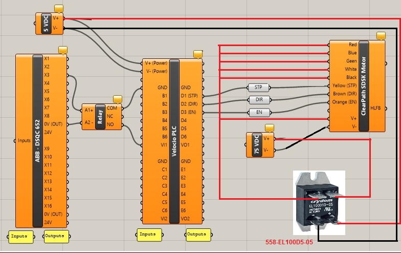
			<content type="html"><![CDATA[<div class="quotebox"><cite>Voltt wrote:</cite><blockquote><p>I&#039;m sorry, I don&#039;t understand... Could you perhaps draw which connections you are taking about?</p></blockquote></div><p>The below image should work. *IF* the blue, green, white, and black wires are supposed to be at the same voltage as MOTOR V+ and V- for your motor in question. </p><p>As long as your 5 volt supply is on the motor and the other wires in red will receive 75 volts from that supply through the relay being controlled by the 5 volt supply. If you need active control of the relay then you could connect it to one of the PLC&#039;s outputs that can handle 3 to 10 volts and have the PLC switch it on and off when needed otherwise with this diagram it will be supplying 75 volts any time the 5 volts is on and no 75 volts when the 5 volts is off.</p><p>That is a Mouser part number for the solid state relay.</p><p><span class="postimg"><img src="http://soliforum.com/i/?0MML36M.jpg" alt="http://soliforum.com/i/?0MML36M.jpg" /></span></p>]]></content>
			<author>
				<name><![CDATA[carl_m1968]]></name>
				<uri>https://www.soliforum.com/user/7731/</uri>
			</author>
			<updated>2018-12-12T15:26:17Z</updated>
			<id>https://www.soliforum.com/post/147880/#p147880</id>
		</entry>
		<entry>
			<title type="html"><![CDATA[Re: Connections between Hardware Components: Need Help !!!]]></title>
			<link rel="alternate" href="https://www.soliforum.com/post/147879/#p147879" />
			<content type="html"><![CDATA[<p>I&#039;m sorry, I don&#039;t understand... Could you perhaps draw which connections you are taking about?</p>]]></content>
			<author>
				<name><![CDATA[Voltt]]></name>
				<uri>https://www.soliforum.com/user/17567/</uri>
			</author>
			<updated>2018-12-12T12:45:20Z</updated>
			<id>https://www.soliforum.com/post/147879/#p147879</id>
		</entry>
		<entry>
			<title type="html"><![CDATA[Re: Connections between Hardware Components: Need Help !!!]]></title>
			<link rel="alternate" href="https://www.soliforum.com/post/147878/#p147878" />
			<content type="html"><![CDATA[<p>Use the plc to control a solid state DC relay rated for greater than 75 volts and switch the 75 to the motor using the relay.</p>]]></content>
			<author>
				<name><![CDATA[carl_m1968]]></name>
				<uri>https://www.soliforum.com/user/7731/</uri>
			</author>
			<updated>2018-12-12T12:21:03Z</updated>
			<id>https://www.soliforum.com/post/147878/#p147878</id>
		</entry>
		<entry>
			<title type="html"><![CDATA[Re: Connections between Hardware Components: Need Help !!!]]></title>
			<link rel="alternate" href="https://www.soliforum.com/post/147877/#p147877" />
			<content type="html"><![CDATA[<p>Okay. 1 set of Connections I&#039;m not sure about are the ones between the Velocio PLC and the Motor. One of the pictures attached gives a sample connection (1) for a different model of Clearpath motor, where all the communication lines and the Power line seem to going to +5V. In my case, the power I want to supply to the motor is 75Vdc ( which is within its operating range of 24-75 Vdc). Are the connections in my setup, correct?</p><p>The connections shown in the sample setup (1), are for motor powered with the same +5V. What would be the connection if we want to power the motor with 75Vdc, and still have it controlled by the same Velocio PLC that is powered by 5Vdc?</p><p>Another connection that I doubt, is the connection between the ABB Controller I/O Card and the Velocio PLC inputs. I notice now that the COM of the relay should be going to one of the inputs (B1,B2, ...). Apart from that, are the connections correct?</p>]]></content>
			<author>
				<name><![CDATA[Voltt]]></name>
				<uri>https://www.soliforum.com/user/17567/</uri>
			</author>
			<updated>2018-12-12T11:26:09Z</updated>
			<id>https://www.soliforum.com/post/147877/#p147877</id>
		</entry>
		<entry>
			<title type="html"><![CDATA[Connections between Hardware Components: Need Help !!!]]></title>
			<link rel="alternate" href="https://www.soliforum.com/post/147851/#p147851" />
			<content type="html"><![CDATA[<p>Hello,</p><p>I need some help with confirming if the connections I intend to make between: <br />&nbsp; &nbsp;my ABB IRC5 Controller&#039;s I/O Card -- Relay -- Velocio PLC (Ace 22) -- ClearPath SDSK Motor<br />are correct or not?</p><p>Details for the components are in the below Links and attached pics:<br />1.&nbsp; <a href="https://www.teknic.com/model-info/CPM-SDSK-3441S-RLN/?model_voltage=75">https://www.teknic.com/model-info/CPM-S … voltage=75</a><br />2.&nbsp; <a href="http://velocio.net/plc-control-clearpath-servo-motor/">http://velocio.net/plc-control-clearpath-servo-motor/</a><br />3.&nbsp; <a href="http://velocio.net/ace/">http://velocio.net/ace/</a></p><p>Pic 1: This is the connections Diagram: x2Scrap00.png<br />Pic 2: This is the Specs for the DO ports on the ABB controller&#039;s I/O Card.<br />Pic 3: Hardware Specs of the Velocio PLC: x2scrap02.png<br />Pic 4: Is the model connection made with a different series motor: x2scrap03</p><p>Could someone help confirm if my connections are correct?</p>]]></content>
			<author>
				<name><![CDATA[Voltt]]></name>
				<uri>https://www.soliforum.com/user/17567/</uri>
			</author>
			<updated>2018-12-11T10:19:41Z</updated>
			<id>https://www.soliforum.com/post/147851/#p147851</id>
		</entry>
</feed>