Topic: Upgrading to the Azteeg X3
The Azteeg X3 controller is equivalent to the RAMPS 1.4 It supports two extruders, 6 endstops, has a built in MicroSD card reader, and has many expansion pins, including support for up to 5 gcode controllable fans or LEDs. Here is the page about it at the RepRap wiki- http://reprap.org/wiki/Azteeg_X3. It is available from http://www.panucatt.com/.
The board comes without headers, which must be soldered on. This gives you the ability to choose straight or angled headers when ordering (it's best to get angled headers). If you haven't soldered anything to a circuit board before, I recommend these tutorials -
http://www.youtube.com/watch?v=J5Sb21qbpEQ Part 1
http://www.youtube.com/watch?v=fYz5nIHH0iY Part 2
If you follow his recommendations for equipment and solder, the job will be much easier than if you try a direct plug-in solder pen and some random solder (ask how I know). Also get some small shrink wrap sleeves for rewiring the endstops.
Read the directions and wiring guide at the RepRap wiki. In addition to the headers for endstops, thermistors, and motors, I recommend getting additional headers to add to the expansion pins while you are at it, especially the area designated for Fans and LEDs. When you want to add features later, they will be ready to plug in.
There are plenty of warnings not to power up the stepper drivers without a motor attached. So if you ordered drivers with the board, put aside the one meant for extruder 2 to keep as a spare, or save it for the day that you design that second extruder mod for the Solidoodle.
The endstops need to be wired differently than they were for the Sanguinololu, both at the endstop and the connector.
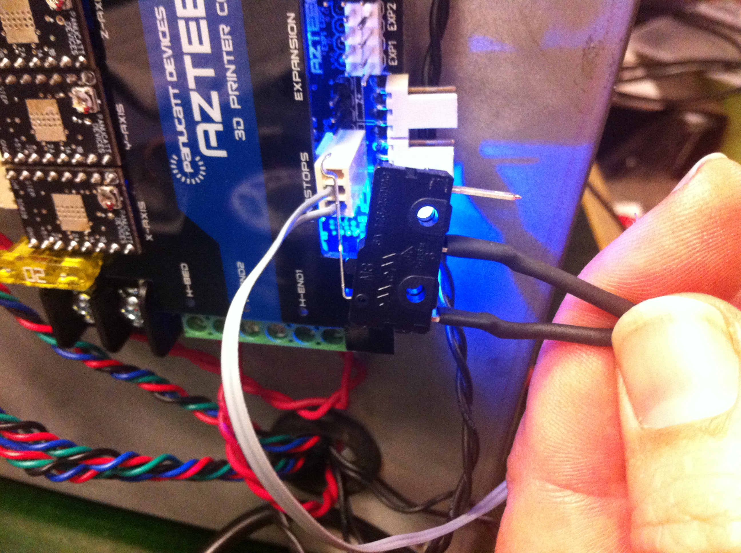
The Common wire needs to go to the left pin of the connector. The other wire needs to move from the Normally Closed (NC) pin on the other end to the Normally Open (NO) pin in the middle. That wire goes to the middle pin on the connector.
There are angled headers on the edge of the board for MIN endstops, and straight headers behind them for MAX endstops. The Solidoodle uses MAX endstops for X and Y, meaning the endstops are placed at the maximum coordinates for those axis (X=150 and Y=150) rather than the minimum coordinates (XY=0). The Z endstop is at minimum, since it is near the extruder at 0.
It is easier to plug the enstops into the Min headers on the edge of the board. To do those, go in to the firmware and tell it to use the Minimum Pins for Maximum endstops-
Follow the directions posted elsewhere for updating firmware. When it is open in Arduino, first go to configuration.h and change
#define MOTHERBOARD 62
to
#define MOTHERBOARD 33
go to pins.h and find the section that starts #if MOTHERBOARD == 33 || MOTHERBOARD == 34
Switch the Pins between Min and Max for the X and Y axis. Change
#define X_MIN_PIN 3
#define X_MAX_PIN 2
to
#define X_MIN_PIN 2
#define X_MAX_PIN 3
and change
#define Y_MIN_PIN 14
#define Y_MAX_PIN 15
to
#define Y_MIN_PIN 15
#define Y_MAX_PIN 14
While you are there, check the fan pin-
#define FAN_PIN 9
If you have a fan mounted in a nozzle duct, you can connect the wires to the screw terminals meant for the second extruder. If you do this, leave the pin set to nine. Alternatively, you can plug the connector into the first header pair in the Fans/LEDs section. If you do that, change the pin to 4. If you can't fit the connector on the first pair, you can plug it onto the last pair in which case you would make it pin 11.
If the motors won't move because it says the endstops are always on, they need to be reversed in configuration.h
change
const bool X_ENDSTOPS_INVERTING = false
to
const bool X_ENDSTOPS_INVERTING = true
for each axis.
If a motor is going the wrong direction, change
#define INVERT_X_DIR false
to
#define INVERT_X_DIR true
for that axis.
The X3 is bigger than the Sanguinololu, so I made some offset standoffs to allow it to be screwed into the exising holes.