1 (edited by adrian 2013-06-15 13:32:22)

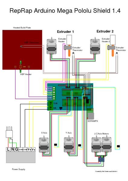
Topic: How-To: Converting to a RAMPS Controller

If you want to add accessories such as multiple PWM Fans, an LCD, multiple extruders or other features, the easiest way to achieve this is to switch to using a RAMPS (RepRap Arduino Mega Pololu Shield).

These boards are available online as a complete kit, with or without LCD and often many other accesories. It is modular in that it sits on top of an Arduino MEGA 2560, allowing future replacement/upgrade without need to alter I/O.

It will, for the most part, bolt straight onto the Solidoodle with 2 specific differences:
a) The Bed and Extruder Heaters are Screw Terminals;
b) The Limit Switches need to change pinout slightly.

RAMPS boards also do not have as many 12V headers exposed, so my Sidecar board seeks to resolve that issue as well.  If you don't care for preserving the 'stock' connections at all, you can obviously simply re-terminate the Limit Switch connectors. I still recommend making up the sidecar board for the additional Power Connectors.

I am using the Sang to RAMPS bracket I made up with the slot for a sidecar board.
http://farm6.staticflickr.com/5349/9025069861_29334e534e_c.jpg. The STL's are available here: http://www.soliforum.com/post/26100/#p26100

Specific Info on RAMPS itself is best sought from the RAMPS Wiki page: http://reprap.org/wiki/RAMPS_1.4

The Sidecar Board:
As mentioned, the RAMPS does have fewer 12V rails exposed. It also required a different physical pinout connection on the Limit Switches that you can't really deal with in firmware. To resolve these issues, I have made the following:
http://farm6.staticflickr.com/5468/9027240370_11ba72c332_c.jpg
http://farm3.staticflickr.com/2878/9027238270_804d766fc2_c.jpg
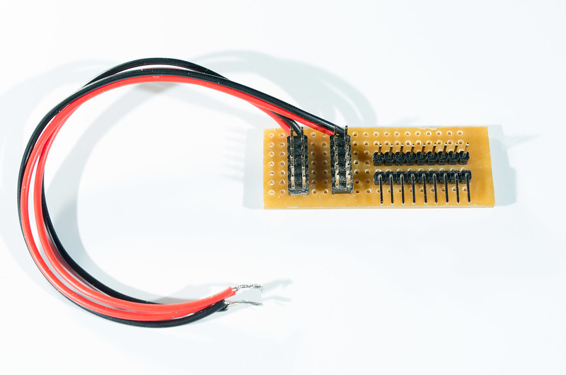
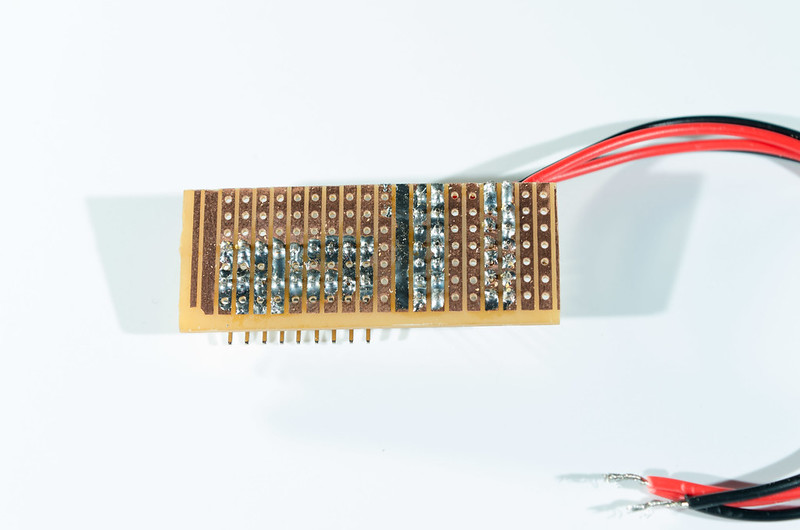
As hopefully should be visible from the pics; it is a very simple board. Using some Stripboard that I cut to 55x25, I have added some Double Row Headers that are installed such that all the left pins are shorted and all the right pins are shorted, and a set of 9 Right Angle and Vertical Pins that have 1 vertical pin shorted to 1 right angle pin. To each of the Double Row header sets, I've added a Red and Black wire. These become 2 power strips that are later connected to my 12V supply (I use a small JST connector to keep it modular, but you can screw it into the input terminals just as effectively).
The Right-Angle/Vertical combos are used inconjunction with a set of 6 Jumper Wires to 'remap' the Limit Switches. This allows me to use the stock connectors but patch them onto the RAMPS limit headers.

Once made up, it slots in quite firmly to the sidecar slot on the bracket, like thus:
http://farm9.staticflickr.com/8554/9027234688_cbafb359eb_c.jpg

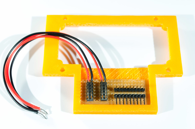
Installing the Bracket and RAMPS Board
1) So after you remove the cover (if you have one or an SD3) from the existing Sanguinololu, the back of your printer probably looks close to this:
http://farm3.staticflickr.com/2807/9047992574_2f2af1d490_c.jpg
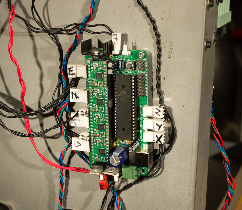
Eagle-Eyed readers will probably not I've removed the Bed Thermistor and Heater and my Sang has a 1284p in place of the 644p, but it should be similar enough.

Finish removing the rest of the Sang.

2) Now you want to first attach the RAMPS to the Bracket before installation. I used 2 M3 30mm Bolts + Nuts, and a Zip Tie on the 'blind' mount hole on the top left of the board when viewed from the USB connector.  Also be sure to remove the 5th Stepper Driver board if your kit came with them pre-installed on the board.

3) When done, mount it to the Solidoodle by using 2 x 10mm M3 screws. I found attaching it at the top right and bottom left corners provides a more than solid mounting to the printer - but feel free to use all 4 mount points.  It should now look something like:
http://farm3.staticflickr.com/2812/9045765991_dd52b3c2de_c.jpg

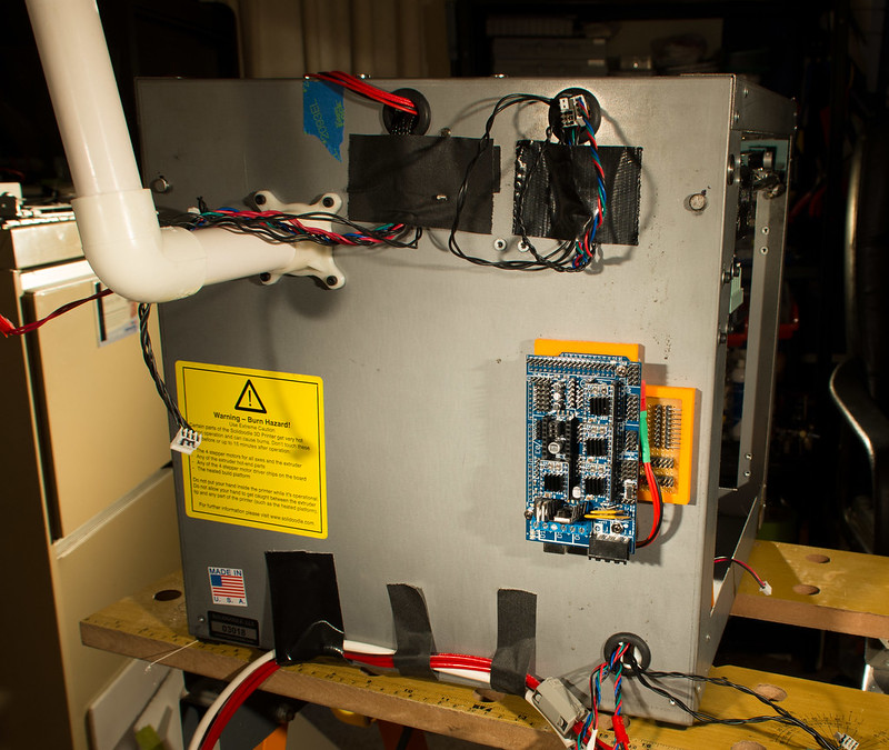
4) To kick things off and get the wires out of the way, hook up your Limit Switches to the Sidecar. If you are choosing to reterminate the wires, then now is a good time to do that instead.
http://farm8.staticflickr.com/7296/9047989016_130fb1d417_c.jpg

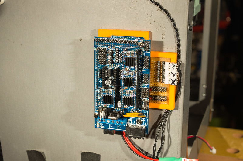
5) Now connect the Motors. The headers are labelled, but when viewed from the USB port, it goes X/Y/Z on the right hand side and the Extruder Motor goes into E0.
http://farm3.staticflickr.com/2827/9045757431_9d9a2c1177_c.jpg

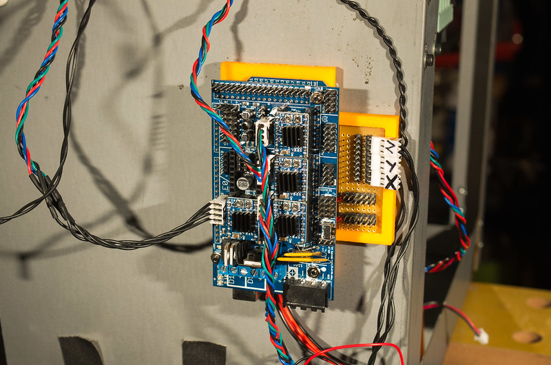
6) Connect the LED Strip and Extruder Stepper Fan to the power strips, or your alternative 12V supply. The + side of the plugs is, when looking at the front of the connector so the wires protrude behind the plug, the right hand side of the plug.
http://farm3.staticflickr.com/2891/9045755655_5a3a897144_c.jpg

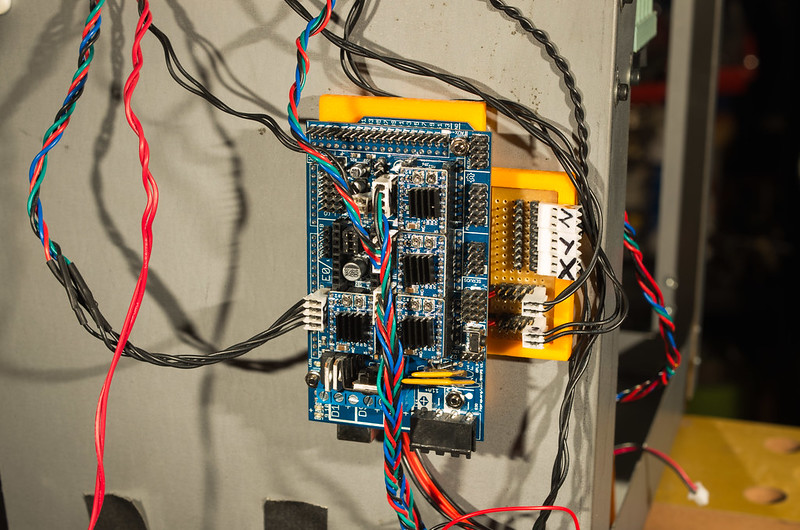
7) Now its time to connect the Jumper Wires from the Sidecar Limit Switches to the RAMPS. If you've reterminated them, nows the time to plug them in directly.

You need to install them using the left most 2 pins for each group, and use the Max position for X and Y, and Min position for the Z Axis. Min is marked by -'s on the silkscreen. The end result should look like this using either the jumpers or the reterminated wires:
http://farm8.staticflickr.com/7379/9045751069_a05c15183a_c.jpg
http://farm3.staticflickr.com/2866/9047975426_e56e41269c_z.jpg

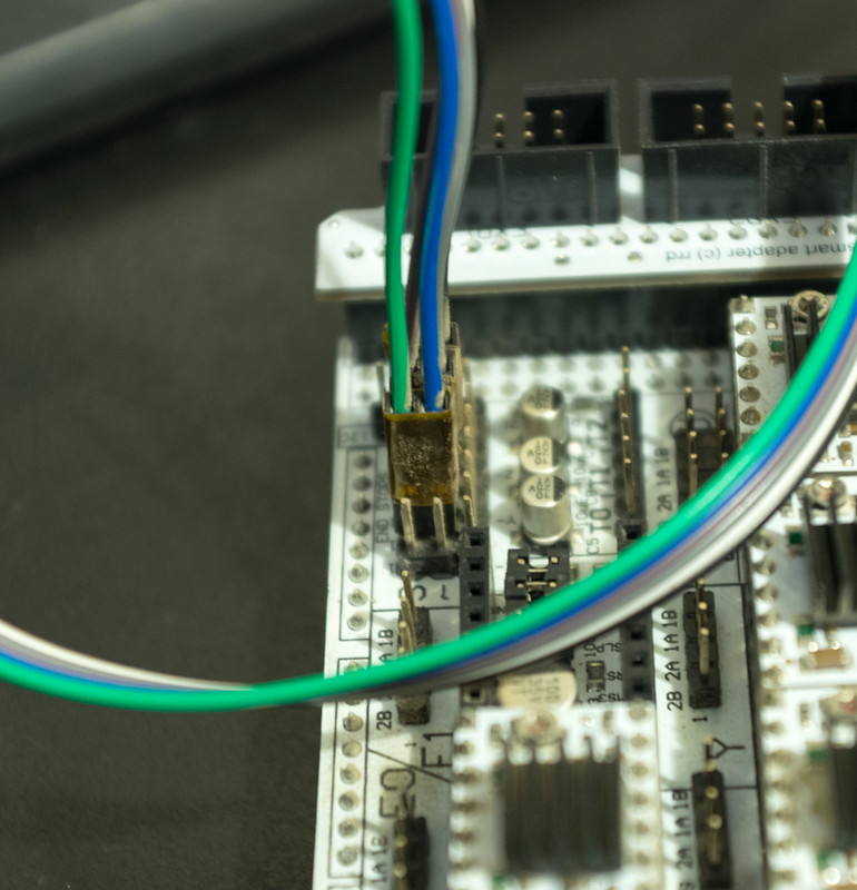
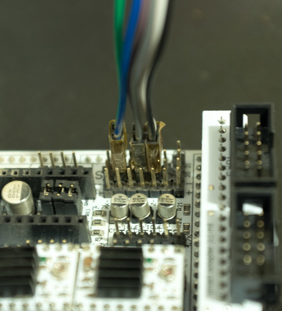
And on the board we are installing:
http://farm3.staticflickr.com/2836/9045747321_2472a14989_c.jpg

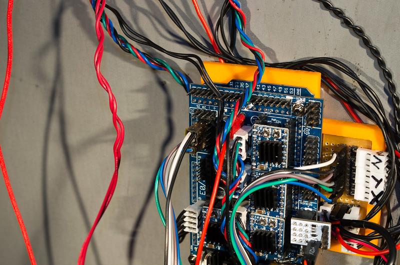
8) Connect the Thermistors. The headers are located just next to the Z-Axis Motor Header. Place the Extruder Thermistor in T0, and the heated bed in T1.  Now is also a good time to screw in the Heated Bed and Extruder Heater. Connect the Bed to the screw terminal labelled D8, and your Extruder into D9. Add your Smart LCD Shield and Fan Extender now if you have one as well:
http://farm6.staticflickr.com/5527/9045741005_d966328a5c_c.jpg

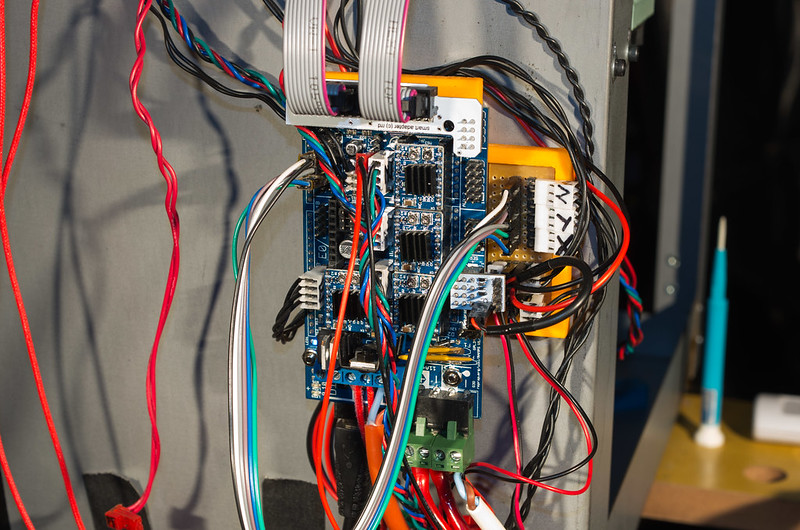
9) Almost Done! Its time to upload your firmware and calibrate your Stepper Currents. Simply download either lawsy's or mine firmware and follow the usual procedures. You want to have Arduino IDE 'Board' set to Arduino MEGA 2560. The minimum changes is to also change Configuration.h under the MOTHERBOARD to 33 or 34.  Use Type 34 if you have a Fan Extender, otherwise use 33. Now verify and upload the Firmware to the Arduino.

10) Set your Stepper Driver VREF voltages. Depending on what type of RAMPS kit you bought, you could have Pololu's, StepSticks or G3D Drivers. You need to confirm what Sense Resistor Value your particular stepper driver has, and then set the VREF according to this table (excuse my lazy screen shot of Excel...):
http://farm3.staticflickr.com/2875/9047990209_d1e314fe16_o.jpg

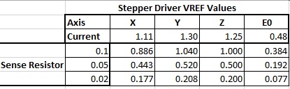
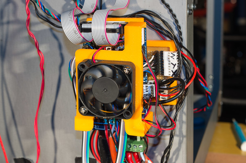
11) Snap on the Fan, and Voila!, You're Done! smile
http://farm6.staticflickr.com/5349/9045738253_2173020a0f_c.jpg

Let me know if something isn't clear, or I appear to have missed something. I'm not the greatest at writing how-to's smile
Higher Res versions of the images and a couple more are available on my Flickr stream: http://www.flickr.com/photos/ozadr1an/

Not sure what 'level' this is either - 2? or 3 ?
Adrian

2

Re: How-To: Converting to a RAMPS Controller

excellent write up Adrian!

3

Re: How-To: Converting to a RAMPS Controller

I was wondering what you had hooked up the the T2 thermistor pins.
http://farm3.staticflickr.com/2836/9045747321_2472a14989_c.jpg

Then I saw you moved it in the next picture smile
http://farm6.staticflickr.com/5527/9045741005_d966328a5c_c.jpg

As Briggs said, excellent write up Adrian! I wish I had this when I was doing mine. I ended up making a lot of extension cables.

SD3 w/ mods:
Glass bed with QU-BD heat pad upgrade, threadless ballscrew w/ 8mm smooth rod, spectra line belt replacement, lawsy MK5 extruder, Lawsy replacement carriage, E3D hotend, Ramps 1.4 w/ reprap discount controller, DRV8825 drivers, 12v 30A PS, Acrylic case, Overkill Y-idlers, Filament alarm, Extruder fan + more.

4

Re: How-To: Converting to a RAMPS Controller

Where do I get this and how much does all this cost?

5 (edited by adrian 2013-06-16 07:24:31)

Re: How-To: Converting to a RAMPS Controller

FatalDischarge wrote:

Where do I get this and how much does all this cost?


Varies. The sidecar board is probably $5 from Radioshack all up including headers.

The RAMPS board, depends what you get.

http://www.ebay.com/sch/i.html?_odkw=RA … p;_sacat=0

You can start for just the RAMPS itself for $20.. but you need an Arduino MEGA 2560.. so if you don't have that, step up to the basic kits that include the RAMPS and the Arduino for $60-$80.

http://www.reprapdiscount.com/

I prefer getting the more complete Kits from the likes of RepRapDiscount, where for between $150 and $200 you can get the RAMPS, LCD Panel (More expensive is the Full Graphic one), Replacement GT2 Pulleys and Belt (good for the X-Axis), SD Card reader and more (like a couple of spare Thermistors etc). Really it comes down to what you want and can use - all of its useful really as spares or for a future 'built from scratch' printer (say you decide to build a Prusa or something).

Gadgets 3D Also have a nice couple of kits, http://gadgets3d.com/ .

Heaps more info on the RAMPS page at under 'Where to get it': http://reprap.org/wiki/RAMPS_1.4

2n2r5 wrote:

I was wondering what you had hooked up the the T2 thermistor pins.

As Briggs said, excellent write up Adrian! I wish I had this when I was doing mine. I ended up making a lot of extension cables.

Cheers guys. Heh, yeah, I parked the thermistor there for a moment to keep the wire out of the way then realised it might confuse people so moved it to the correct location smile T2 is used for reference for the second extruders Thermistor (for other readers).

6

Re: How-To: Converting to a RAMPS Controller

If you switch from the printrboard to the ramps 1.4
will I need to replace all the stepper motor controllers to the DRV8825?

Powder coated steel enclosure, 1/4" Surface grounded hardened aluminum plate, MK2A Heat bed, .200 Polished fused quartz plate, Machined quick change hot bed mount, E3D hot end, Ramps 1.4, DRV8825 stepper motor drivers

7

Re: How-To: Converting to a RAMPS Controller

I am thinking of upgrading to the Azteeg x3

http://www.panucatt.com/Azteeg_X3_repra … ax33dp.htm

Ultimaker S3.

8

Re: How-To: Converting to a RAMPS Controller

techbuilder2175 wrote:

If you switch from the printrboard to the ramps 1.4
will I need to replace all the stepper motor controllers to the DRV8825?

See this post on only using 8825 on the extruder.
http://www.soliforum.com/post/33374/#p33374

But the printrboard doesn't have removable A4988 stepper drivers, so you would need new steppers anyway.

9

Re: How-To: Converting to a RAMPS Controller

Pardon my ignorance please, but what is that little white board you have plugged in over your servo pins on the ramps board?

SD2 w/ mods: Rumba controller, ATX PSU, SD pro case, glass bed, with more to come...

10

Re: How-To: Converting to a RAMPS Controller

Beautiful write up. This should be a sticky, IMO, like all such how-to's.

Robox printer, HICTOP (Prusa i3 variant) Model 3DP17 printer, ELEK 2.5W laser engraver, AutoDesk 123D Design, Windows 10

11

Re: How-To: Converting to a RAMPS Controller

DigitalWhitewater wrote:

Pardon my ignorance please, but what is that little white board you have plugged in over your servo pins on the ramps board?

"Fan Extender"... Long winded name for a PWM Multiplier that gives you 2 x GCode PWM Fans for use when you have both the 2 x Extruder slots in use.

Heartlander wrote:

Beautiful write up. This should be a sticky, IMO, like all such how-to's.

Cheers smile

12

Re: How-To: Converting to a RAMPS Controller

Heartlander wrote:

Beautiful write up. This should be a sticky, IMO, like all such how-to's.

1++

SD2 w/ mods: Rumba controller, ATX PSU, SD pro case, glass bed, with more to come...

13

Re: How-To: Converting to a RAMPS Controller

Love this... I want it?  Where can i buy this in England?

Will this board allow the use of two z  steppers?

Also i want to use duel extruder and possibly three extruders is this possible?

Kind regards

14

Re: How-To: Converting to a RAMPS Controller

Yes, 2 z motors and 2 extruders (not 3).  Though I have a fan connected to the second extruder power output.

Plenty of online retailers.

http://reprap.org/mediawiki/images/thumb/6/6d/Rampswire14.svg/424px-Rampswire14.svg.png

15 (edited by adrian 2013-11-16 23:58:23)

Re: How-To: Converting to a RAMPS Controller

Staffordknot wrote:

Love this... I want it?  Where can i buy this in England?

Ebay - but see my comment re RUMBA board...

Staffordknot wrote:

Will this board allow the use of two z  steppers?

Yes. Either with two seperate drives (sounds great, isn't really, as you face 'sync' issues then wink ) or by just plugging in two steppers to the same driver.

Staffordknot wrote:

Also i want to use duel extruder and possibly three extruders is this possible?
Kind regards

Dual yes, Tri no. For Tri, you are much better getting the RUMBA board from RepRapDiscount. Its a RAMPS+Arduino on one PCB, with up to 6 stepper drivers, 6 heaters and 3 PWM fan outputs.

I've switched to Rumba boards over RAMPS types the past 3 months...
http://www.ebay.co.uk/itm/RUMBA-KIT-inc … 2a33b187e2  .. I personally choose to buy it straight from RRD - as they developed it, ran the indiegogo campaign etc.

Even if you dont want the Tri-Extrusion, the Rumba has better quality components (better heat sinking, all SMD, all correctly rated wink ) over the RAMPS these days.. hence why I've switched to them

16

Re: How-To: Converting to a RAMPS Controller

adrian wrote:

10) Set your Stepper Driver VREF voltages. Depending on what type of RAMPS kit you bought, you could have Pololu's, StepSticks or G3D Drivers. You need to confirm what Sense Resistor Value your particular stepper driver has, and then set the VREF according to this table (excuse my lazy screen shot of Excel...):
http://farm3.staticflickr.com/2875/9047990209_d1e314fe16_o.jpg

I'm about to install the RAMPS in my printer this weekend, but after I read the paragraph above I still have a few more questions:

1.  How can I tell which steppers I have? They look like Palolu's, but how can I tell the difference. (Below is what the stepper looks like)
2.  How can I determine the sense resistor value?
3.  How do I measure the VREF (at which pins/location)
4.  I also have a 8825 StepStick.  These are from GeeTech.  Can those be used straight up, or do I have to do the resistor hack to make them work.

http://www.soliforum.com/misc.php?action=pun_attachment&item=4756

Thanks in advance.

Post's attachments

stepper.jpg 73.33 kb, file has never been downloaded. 

You don't have the permssions to download the attachments of this post.
To print or, 3D print, that is the question...
SD3 printer w/too many mods,  Printrbot Simple Maker Ed.,  FormLabs Form 1+
AnyCubic Photon, Shining 3D EinScan-S & Atlas 3D scanners...
...and too much time on my hands.

17

Re: How-To: Converting to a RAMPS Controller

1. They are a4988 . Can tell by size of driver IC.
2. By looking and decoding the number on it... but try 0.05 for starters... it'll be right or the motor will tick loudly at idle and get hot... or ask where you sourced it.
3. Measure from the trimpot itself to the ground pin to the left of it is best.
4. I use mine all straight, and have no issues. But can't comment on the gee tech specifically

18 (edited by pirvan 2014-03-01 19:02:04)

Re: How-To: Converting to a RAMPS Controller

Can I bench test the values by just having it plugged into the USB (5V), or do I need to have everything connected including the motors?

On a side note, why are the values different on the X & Y.  I can see then being potentially different on the Z and E, but I would think that X & Y should have the same values.


Edit:  I'm wiring the RAMPS to my printer as aI write this, and I've been using both the images above and the Wiring diagram on the RAMPS 1.4 Wiki page as reference.  I noticed you wired the Extruder Heater (E0) to D9.  The wiki diagram shows extruder heater E0 connecting to D10, and E1 to D9.  I assume this is because you're using the fan extender.

Since I'm not currently using a Fan extender, I think I need to connect the extruder to D10, and the G-code controlled fan to D9, correct?

To print or, 3D print, that is the question...
SD3 printer w/too many mods,  Printrbot Simple Maker Ed.,  FormLabs Form 1+
AnyCubic Photon, Shining 3D EinScan-S & Atlas 3D scanners...
...and too much time on my hands.

19 (edited by adrian 2014-03-01 22:17:11)

Re: How-To: Converting to a RAMPS Controller

Don't test values without motors connected and powered.

X & Y have two different sized motors... X is a 1.0amp NEMA14, and Y is a 1.1(?) amp NEMA17 . Hence they are different smile

depends on your firmware re fan pin - I actually made extruder always D9, and use D10 for second extruder/fans.. otherwise it does annoying swapovers between board 33 and board 34... anyway its just a setting in firmware and they are hardware wise identical.

20

Re: How-To: Converting to a RAMPS Controller

OK, everything is connected and running.  Here is what I found so far:

My sense resistor value must be 0.1, because with the trimpots in the middle, I read ~750mV.  With that value, the "Z" axis can only move the bed down, it can't bring it back up.  The "X" & "Y" can move the carriage 10mm at the time but if I ty to move 100mm or home the axis, it freezes up.

Anyway, I used the values for a 0.1 sense resistor and everything seems to be moving fine.  One thing I noticed is the homing behavior is different than before.  It no longer re-zeroes after hitting the end stops.  Is this normal?

Here is my installation:

http://www.soliforum.com/misc.php?action=pun_attachment&item=4762

Post's attachments

RAMPS installation.jpg
RAMPS installation.jpg 403.81 kb, 1 downloads since 2014-03-02 

You don't have the permssions to download the attachments of this post.
To print or, 3D print, that is the question...
SD3 printer w/too many mods,  Printrbot Simple Maker Ed.,  FormLabs Form 1+
AnyCubic Photon, Shining 3D EinScan-S & Atlas 3D scanners...
...and too much time on my hands.

21

Re: How-To: Converting to a RAMPS Controller

pirvan wrote:

One thing I noticed is the homing behavior is different than before.  It no longer re-zeroes after hitting the end stops.  Is this normal?

Thats just a firmware setting - not sure why it would have been flipped.. anyway... in Configuration_adv.h check the lines

//homing hits the endstop, then retracts by this distance, before it tries to slowly bump again:
#define X_HOME_RETRACT_MM 5 
#define Y_HOME_RETRACT_MM 5 
#define Z_HOME_RETRACT_MM 5 //{SD Patch}
#define QUICK_HOME  //if this is defined, if both x and y are to be homed, a diagonal move will be performed initially.

Which firmware you using as a base and when did you download it ? it would seem to be set correctly in the latest community beta's....

22

Re: How-To: Converting to a RAMPS Controller

Crap... the frigging extruder is moving backwards.  It's plugged in correctly, but when I hit extrude it retracts and vice-verse.

I just looked at some pictures I took before and sure enough, the extruder is plugged in backwards on the original Sanguinololu.  What the hell...  Why would Solidoodle do that.

Is there a way to reverse that in firmware?

To print or, 3D print, that is the question...
SD3 printer w/too many mods,  Printrbot Simple Maker Ed.,  FormLabs Form 1+
AnyCubic Photon, Shining 3D EinScan-S & Atlas 3D scanners...
...and too much time on my hands.

23

Re: How-To: Converting to a RAMPS Controller

pirvan wrote:

Crap... the frigging extruder is moving backwards.  It's plugged in correctly, but when I hit extrude it retracts and vice-verse.

I just looked at some pictures I took before and sure enough, the extruder is plugged in backwards on the original Sanguinololu.  What the hell...  Why would Solidoodle do that.

Is there a way to reverse that in firmware?

yes - there is a section

#define INVERT_X_DIR false    // for Mendel set to false, for Orca set to true {SD Patch}
#define INVERT_Y_DIR false    // for Mendel set to true, for Orca set to false
#define INVERT_Z_DIR false     // for Mendel set to false, for Orca set to true {SD Patch}
#define INVERT_E0_DIR true   // for direct drive extruder v9 set to true, for geared extruder set to false
#define INVERT_E1_DIR true    // for direct drive extruder v9 set to true, for geared extruder set to false
#define INVERT_E2_DIR true   // for direct drive extruder v9 set to true, for geared extruder set to false

Flip the invert on the E's ... or reverse the motor (solidoodle reversed it so they didn't have to remember the firmware status) - its the same thing either way ultimately so either approach works...

24

Re: How-To: Converting to a RAMPS Controller

adrian wrote:
pirvan wrote:

One thing I noticed is the homing behavior is different than before.  It no longer re-zeroes after hitting the end stops.  Is this normal?

Thats just a firmware setting - not sure why it would have been flipped.. anyway... in Configuration_adv.h check the lines

//homing hits the endstop, then retracts by this distance, before it tries to slowly bump again:
#define X_HOME_RETRACT_MM 5 
#define Y_HOME_RETRACT_MM 5 
#define Z_HOME_RETRACT_MM 5 //{SD Patch}
#define QUICK_HOME  //if this is defined, if both x and y are to be homed, a diagonal move will be performed initially.

Which firmware you using as a base and when did you download it ? it would seem to be set correctly in the latest community beta's....

How can I tell?? 

I downloaded the Solidoodle-Arduino 1.0.5 windows.  The files in the /examples/SolidoodleMarlin folder are dated 8/4/2013.

To print or, 3D print, that is the question...
SD3 printer w/too many mods,  Printrbot Simple Maker Ed.,  FormLabs Form 1+
AnyCubic Photon, Shining 3D EinScan-S & Atlas 3D scanners...
...and too much time on my hands.

25 (edited by adrian 2014-03-02 03:03:55)

Re: How-To: Converting to a RAMPS Controller

doesn't really matter - was just curious where the settings you had originated from...

Just make sure the lines above are uncommented ; and regarding the inverting steppers - just set it either way and test it - worst that happens is the extruder goes backwards or the right way smile