Topic: Thermal Images of Various Bed Setups
Ok, so I had a busy weekend. I've gone through and captured a bunch of Thermal Camera Images of various Solidoodle Beds. In total, I have so far sampled:
Standard Solidoodle 3 Bed
Standard Solidoodle 3 Bed with Glass
Standard Solidoodle 3 Bed with a Ceramic Tile
RepRap PCB MkIIB Heated Bed with Glass
RepRap PCB MkIIB Heated Bed with a Ceramic Tile
QU-BD 200x200 Square Silicone 12v Heated Bed
QU-BD 200x200 Square Silicone 12v Heated Bed with Glass
QU-BD 200x200 Square Silicone 12v Heated Bed with a Ceramic Tile
If this is all TL;DR for you, the overall winner in my mind is the QU-BD w/ Ceramic Tile due to its power consumption vs speed vs consistency; but we will cover that in more detail below.
First up, for the complete collection of images, check the collection on my Flickr stream at http://www.flickr.com/photos/ozadr1an/c … 363000099/. PDF Reports for all the various Sample Sets are available as a zip file at https://docs.google.com/file/d/0B7Ieezi … sp=sharing. You can also find all the raw thermal image files (to be used with the Testo IR Software - Available from Testo's website) at https://docs.google.com/file/d/0B7Ieezi … sp=sharing
There's over 125 thermal images across all the tests, so in the interests of brevity, I will summarise the key points on each sample set and if you want to examine a solution further, please review the PDF Reports which feature for the most part a full set of heat-up and cool-down pics (the later for interest if you leave a piece on the bed with regard to warping etc during cool-down).
One thing to bear in mind - the reports are more 'qualitative than quantitive'. What this means is - the comparison between temps in a pic is accurate, but the precise temps themselves can be off by a few degrees due to the vastly different 'emissivity' of the surfaces sampled. So don't focus so much on the raw data values - rather focus more on the sample across a test set and local to a particular image. I have also, in the interests of trying to make it easier to interpret, set the temperature scales on each set of images to be the same and therefore the 'legend' for each set to represent the same. So the "Red" on all images of a set should represent the same temperature zone for that set - this makes for a better comparison across the set for what heats up where and when.
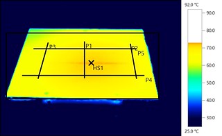
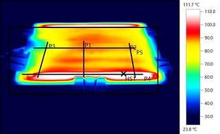
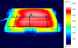
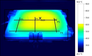
The P1-P5 lines are for temp profiles, detailed in the PDF files. The HS1 "X" refers to the Hot Spot for each image (or the highest temp recorded).
In testing, I was looking for uniformity of temperature and for a nice slow cool down to avoid rapid cooling and thus warping/cracking. I can't hope to live up to a "lawsy" report, but heres what I found:
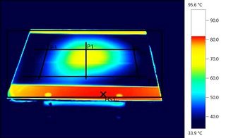
Standard SD3 Bed
In brief, its what we all know. Its slow to heat up and has poor uniformity, with almost a 15°C deviation across the surface. Its hot spot, marked as HS1, is the one bright spot of uniformity - always in the center of the bed with the heat falling off as you approach the edges of the plate. Overall, the least performing of the tested set.
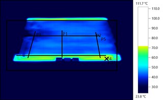
"Hot" Bed, and Bed during Warmup (still with the 15°C deviation across the surface):
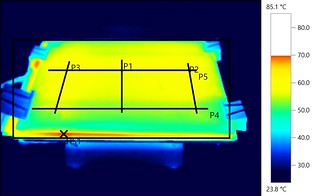
Standard SD3 Bed w/ Glass
This is the most recommended option for people, and you can appreciate to some degree why when looking at the images. It offers a much larger and consistent temp zone, with the drop off limited to the extreme corners. You'll note with almost all combinations that the rear-left corner is consistently the worst performing zone on the standard bed - unsurprising given this is where the electrical connections are.
The glass lags behind the bed some 5°C-10°C, but the reason for its better performance is the consistency and uniformity of that fractionally lower temp. You'll also note the Hot Spot is now at the junction between the glass and the bed itself rather than in the bed center.
Its a clear improvement over the plain bed - but it still highly focuses the heat towards the center and has very sharp and rapidly fall off towards the edges.
"Hot" Bed with Glass, and during warmup. 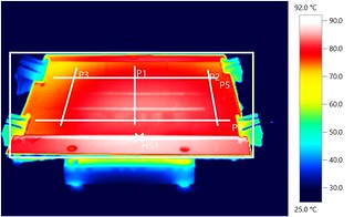
And here you can see it clearly heating from the center out and observe the lag to the aluminium bed itself. This is what causes cracking in larger models left on a cooling glass plate I believe: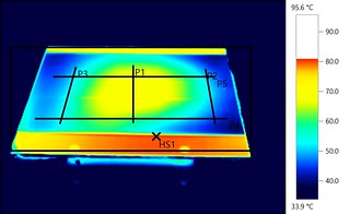
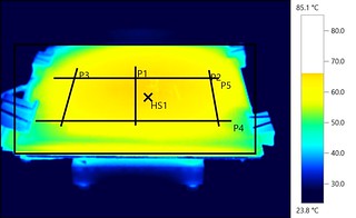
Standard SD3 Bed w/ Ceramic Tile
Less common, but my previous favorite. I found from my own empirical testing that using a ceramic tile provided a much more uniform temp area and a far kinder cool-down cycle due to its greater thermal mass over glass. I had parts warp and split during cool-down on a glass bed when I had the bed setup to switch off at job completion over night, but once I switched to a tile I never had that issue again. It does however, have even more thermal lag than the glass - it takes a bit more effort to get it to temp, but once there, it stays extremely consistent.
"Hot" Bed with only a 10°C deviation despite the colour variations, and during various warmup phases. You'll note that there is a much larger and consistent 'hot' area.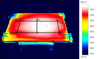


PCB Mk2B Heated Bed w/ Glass
The 200x200 reprap heated bed proved pretty effective, with rapid heatup in under 10 minutes. However, it sucked almost 12 Amps to do that and even when PID tuned, suffered a fair amount of overshoot. It peaked at 112°C on one test when aiming for a 95°C set point... long term not sure how well it will survive before burning some of the FR4 base. As this board is configured to be a set of snaking tracks from the base, it also recorded the Hot Spots to be well focused towards the end with the terminal connections whilst the thermistor itself is located centrally - no doubt leading to the huge overshoot as the PID lagged quite a bit initially before the thermistor reached the set-point.
Overall however, it has a huge 'hot area' compared to the standard bed, but still quite sharply falls off at the edges to almost the same degree as the standard bed. The Hot Spot also roams around and is never actually in the bed center. It is however, pretty darn consistent with only the outer edges being where it starts to fall away.
The bed sitting at its set point of 95°C but you can see the higher bed temp underneath, and during the warm up cycle where the center of the bed went all the way to 105°C before coming back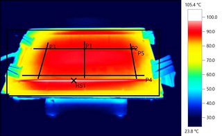

Good even heat up phases though;
PCB Mk2B Heated Bed w/ Ceramic Tile
A great performer in the thermal mass stakes here. Showed so far one of the biggest and most consistent hot spots with fall off limited to the extreme edges and corners. Had a 10°C lag to the Set Point of 95°C peaking at only 85°C - but had so far one of the biggest consistent hot zones of all the tests with a very slight fall off as you moved out before you reached the extreme edges. Its cool down was also fantastic with a nice even zone the whole way through - If I didn't have a QU-BD this would be my preferred bed setup. It definitely had the largest hot zone - but its huge over shoot even when PID tuned would cause me concern regarding its longevity.
At temp (the weird blobs are excessive hairspray blobs since I didn't clean the tile up from about a weeks worth of printing on it) and during heat up. Note the central HS mark on the hot plate and the very consistent warmup phase: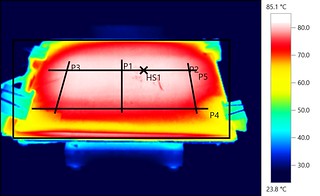
And during the extremes of heat up (left) and cool down (right), you can see how consistent the surface remains with the hot spot staying in the middle during cool-down. This is what makes the tile superior to the glass plate in my opinion and avoids uneven cooling in a model:
QU-BD 200x200 12v Silicone Heated Bed
Well this one was just FUN to watch as the internal elements glowed like a neon sign when you switched it on in the thermal camera ![]() Once again like the PCB Mk2B, the initial heat focus comes from just east of the electrical connections but due to the thinner and 'doubled back' elements compared to the PCB Mk2B it seemed to spread the heat a lot wider a lot quicker. But the bed is pointless without a top surface, so heres just a few pics to explain why it looked cool
Once again like the PCB Mk2B, the initial heat focus comes from just east of the electrical connections but due to the thinner and 'doubled back' elements compared to the PCB Mk2B it seemed to spread the heat a lot wider a lot quicker. But the bed is pointless without a top surface, so heres just a few pics to explain why it looked cool ![]()


QU-BD 200x200 12v Silicone Heated Bed with Glass Plate
The first of the useable options with the QU-BD, our old friend 'Glass'. I had setup PID on the QU-BD, so I can't explain why, but adding the glass on top caused the QU-BD to overshoot badly, much like the PCB Mk2B had. But it didn't when it was by itself or when it had the ceramic tile, so I'm at a loss to explain what the glass does besides hypothesizing that its transferring the heat much faster than either a bare QU-BD or a QU-BD with ceramic tile. More research to be done here I thinks. Glass showed much the same traits as under the PCB MK2B, with perhaps even more 'blotching' in the hot zone. It didn't have even fall off, instead going through several 'hot-cooler-hot-cooler-hot-cooler' bands - I think this could lead to even worse warping than the standard bed. It also displayed even sharper fall off - some 20°C between the hotzones and the glass edges. The Hot Spot was also never in the center. Fast heat up time though, but poor consistency at the set point.
At the set point you can see the very inconsistent hot zone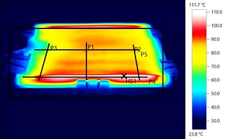
Here you can also see the rapid fall off during cool-down, and the splotchy heat up cycle: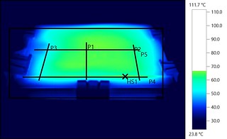
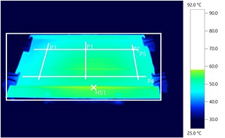
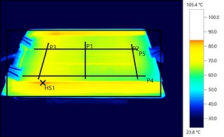
QU-BD 200x200 12v Silicone Heated Bed with Ceramic Tile
The outright winner for me. Rapid heat up, large even hot zone, almost central hot spot and slow and even cool down. What more could you want in a hot bed! I really can't say enough good things about this combo! You can see from the size of the white patch how huge the hot zone is and the cool down took forever, which in my experience would almost eliminate cracking/warping/separation during the cool down phase. 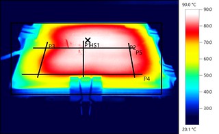
Here you can see just how even and slow it is during cool down, maintaining an almost central hot spot and superbly even temp across the whole plate. 
So this is why the QU-BD + Ceramic Tile is the my new standard for heated print bed solutions.
Well thats more than enough images/info. If you want detailed info on the various test methods - please download the PDF Reports linked above. In there you can find plots across the P1-P5 lines to give you a better idea of fall off etc. The larger images of all 125 odd pics are on my flickr account. Please let me know at least if you found this info helpful/interesting - if it was, i'll try and capture some more sample combinations etc. If anything, it'd just be nice to know if this was of benefit to anyone else. I'll shortly post up a separate thread on the Thermal Extruder images as well.
Adrian
