Topic: [HOWTO] Convert Da Vinci Jr to RAMPS 1.4
Last updated: Aug 7th 2016
Hey guys. I just completed a Da Vinci Jr to RAMPS 1.4 conversion, and I've had a lot of success (and learned a lot from it) and wanted to share my story. I hope this helps some of you who may be struggling with, and/or considering a conversion, and maybe it'll inspire a few tinkerers to follow a similar path.
I'm going to post this in segments because it would take too long to write it all up at once. I'll try to keep it organized though, and eventually compile it into one big how-to if I can.
Everything I'll post here is something I actually did or tested myself. I won't make any untested speculations or link to any products that I didn't actually use without making that clear.
This first part will focus on the the reasons to upgrade and what you'll need. Next I'll talk about getting your Da Vinci Jr ready for conversion, constructing the needed items, plugging it all together, and finally configuration and calibration.
Part 1: What will I need and why do it?
First off, what are some reasons to consider an upgrade?
You can stop messing with the stupid NFC chips. What's better than being able to reset the chips? Not needing a chip to start with
Your machine doesn't work right (assuming it's a software problem instead of a true hardware problem)
You're dissatisfied with the quality of your prints (again assuming it's really a software problem and not hardware)
You want more control over your printer, like the ability to inject arbitrary gcodes, change firmware, adjust your stepper power or values, etc., etc.
You don't care about, or have, your warranties
You, like me, broke your firmware and need to unbrick your machine somehow (and you agree with all of the above)
What are some good reasons not to upgrade?
There are quite a few good reasons to not bother upgrading:
You're happy with the performance of your Jr
You're not bothered buying XYZprinting's chipped filament, and either accept the fact that you're locked into it, or you are happy using a workaround to use other filaments.
You have a printing workflow you like and don't need (or want) any more control over your printer than you have (And no, I'm not being sarcastic. Having an easy-to-use consumer-level machine that "just works", assuming yours works, is perfect for some people.)
You have no knowledge of electricity or electronics, are afraid of them, or otherwise are unable or unwilling to learn about them. I doubt this applies to many of the people reading this.
You don't have the cash to upgrade (But think hard about whether you have the cash to keep buying XYZprinting's expensive filament? An upgrade of this type realistically shouldn't cost much more than a couple spools of filament.)
What should I expect? How long will it take?
This totally depends on your goals and the time you have to devote to it. I upgraded my machine over about a three-week period, working about 30-60 minutes a day on it. I also ran into several problems along the way (OK, I broke stuff that I had to fix). With full, proper guidance and not a small amount of care you can probably upgrade your machine with about 10-12 hours work.
My goal in my conversion was to keep it as clean as possible and avoid being destructive. That means that even though my original board no longer worked (I accidentally bricked the firmware, not fried the electronics), I wanted to avoid any cutting, desoldering or drilling of the original equipment.
If you don't care about destroying original equipment or leaving things a little disorganized, then you might be able to achieve the conversion a little faster. About half the time I spent on mine was spent "cleaning up" and finding neater ways to do things.
What do I need?
Absolutely essential equipment for a successful conversion includes the following:
* A RAMPS 1.4 board. I bought mine from Amazon (https://amzn.com/B0111ZSS2O). Mine has a RepRap Full Graphic LCD. There are other options out there, but any RAMPS 1.4 should work with my procedure. You'll just change your Marlin configuration toward the end.
* Some kind of power supply for the RAMPS board. You have a few options here: you can buy a new one just for the RAMPS, or you can hook up the stock Da Vinci Jr power supply by either cutting the connector off the end, or do what I did and solder up a compatible power connector to tie into the board. Either way it needs to supply at least 5A at 12V (60W total) to match the stock equipment.
* At least 3 each 220 ohm and 12k ohm resistors (the 12k is a little bit flexible; I only had 10k on hand and they work fine, but you don't want to lower this value too much. Better to use slightly larger values for safety if you have some lying around but don't have 12k.) You'll want another 12k (or similar-valued) resistor for the light bar if you're hooking that up.
* Some kind of wire (at least 26 awg solid wire, but 24 awg or larger stranded wire is used in a few places). Make sure it's of sufficient gauge to carry the current load, which is particularly important for the nozzle heater and the RAMPS 1.4 power supply screw terminal.
* Wire cutters and/or strippers
* A digital multimeter, or at least an ohmmeter and voltmeter
* Torx driver (not sure of the size, will update this later). All the Torx bolts are the same size; check the ones that hold down your LCD panel if you're not sure.
* Hex driver (3mm?). The two bolts that hold the filament holder to the frame are hex slots.
I happened to have most of the basic equipment (including resistors and the power jack connector) on hand already, but those items can be picked up cheap at a local electronics/hobby store.
Helpful, but not strictly necessary items you might want:
* A breadboard and flexible jumper kit. Something like these: https://amzn.com/B01BV2A54G and https://amzn.com/B0040Z1ERO.
These are very useful for prototyping your connections to make sure things work before finalizing anything. Smaller jumpers than these can be used to break out of the stock 2.0mm JST connectors (something like these, though please note I didn't actually buy this item and can't vouch for it: https://amzn.com/B005TZJ0AM I used similar jumpers, and another breadboard, that came with a Raspberry Pi breakout kit: https://amzn.com/B01CZDKFLS). Be aware that some jumpers have pins that are slightly too large to fit well into the 2.0mm JST connectors.
These items are definitely optional, but I used them to achieve a non-destructive, "clean" conversion:
* 2.0mm JST connector kit: https://amzn.com/B00B6WBHGC These are for making connectors that can mate with the stock 2.0mm connectors (note that I couldn't locate a kit that included true "male" connector housings and pins, so I actually used the headers included in this kit that are meant for PCB mounting to jump between the two female connectors -- not the strongest connection but it does the trick with a little electrical tape around it to prevent it pulling out).
Without these you'll either have to cut and strip the stock connectors, or use jumpers to break out into a breadboard or custom PCB.
* 2.54mm Dupont connector kit: https://amzn.com/B012EOO9Q0 These are used to mate your custom-made cables to the RAMPS board. If you're using jumpers for your final conversion you can just use those instead.
* If you're using either of the above, you'll need some kind of connector crimper: https://amzn.com/B00OMM4YUY Or you could just use needle-nose pliers if you feel like doing it the hard way. This crimper I used is chunky and sometimes a little awkward to use on the 2.0mm pins, but it didn't produce a single bad connection.
* Ribbon cable for the connector wire: https://amzn.com/B007R9SQQM. There are other options here (including using individual wires), but this produces nice and neat (not to mention colorful) cables. This one spool contained more than enough for the job, even with me screwing up and having to re-make a few cables.
I believe this is 28 awg, so using it for the heater at 2.0A is pushing the spec (1.4A) a bit, but I haven't had any problems with resistive heating and my hot end is working fine. If you're concerned about the gauge you can look for a 26 awg option or double up on those conductors.
How well will it work?
Post-conversion, your printer should work at least as well as the stock Da Vinci Jr. If like me the Jr is your first printer, then there will be a small learning curve to get used to RAMPS, adjust the gcodes to your needs and get things working just right, but less than 48 hours after completing the conversion I'm achieving results comparable to what I got with stock firmware using the same slicing software (Slic3r is my choice currently). If you've been using XYZware for slicing up until now you should expect some additional learning curve to learn Slic3r or Cura or something else. XYZware naturally won't work with your printer post-conversion.
Update: A week post-upgrade, my printer's working perfectly. I'm very happy with the results!
What won't work?
XYZware, as mentioned above. While you could still use it for slicing and then convert your .3w files back to .gcode, I don't see any reason to do that except maybe as a transitional step while learning another slicing package.
The NFC reader. I know, what a shame. The only downside (if you see it as such) is that you'll have to manually set the temperature for your filament in your slicing software from now on.
The Jr includes some kind of 4-pin filament detector that I haven't bothered to hook up yet. RAMPS 1.4 seems to support a filament run-out sensor so it may be possible to get this working, but honestly it's an optional component that I just haven't been motivated to mess with.
That's all. I'll even explain how to hook up the internal light bar and control it with gcode so you can switch it on/off during your print
How will it look?
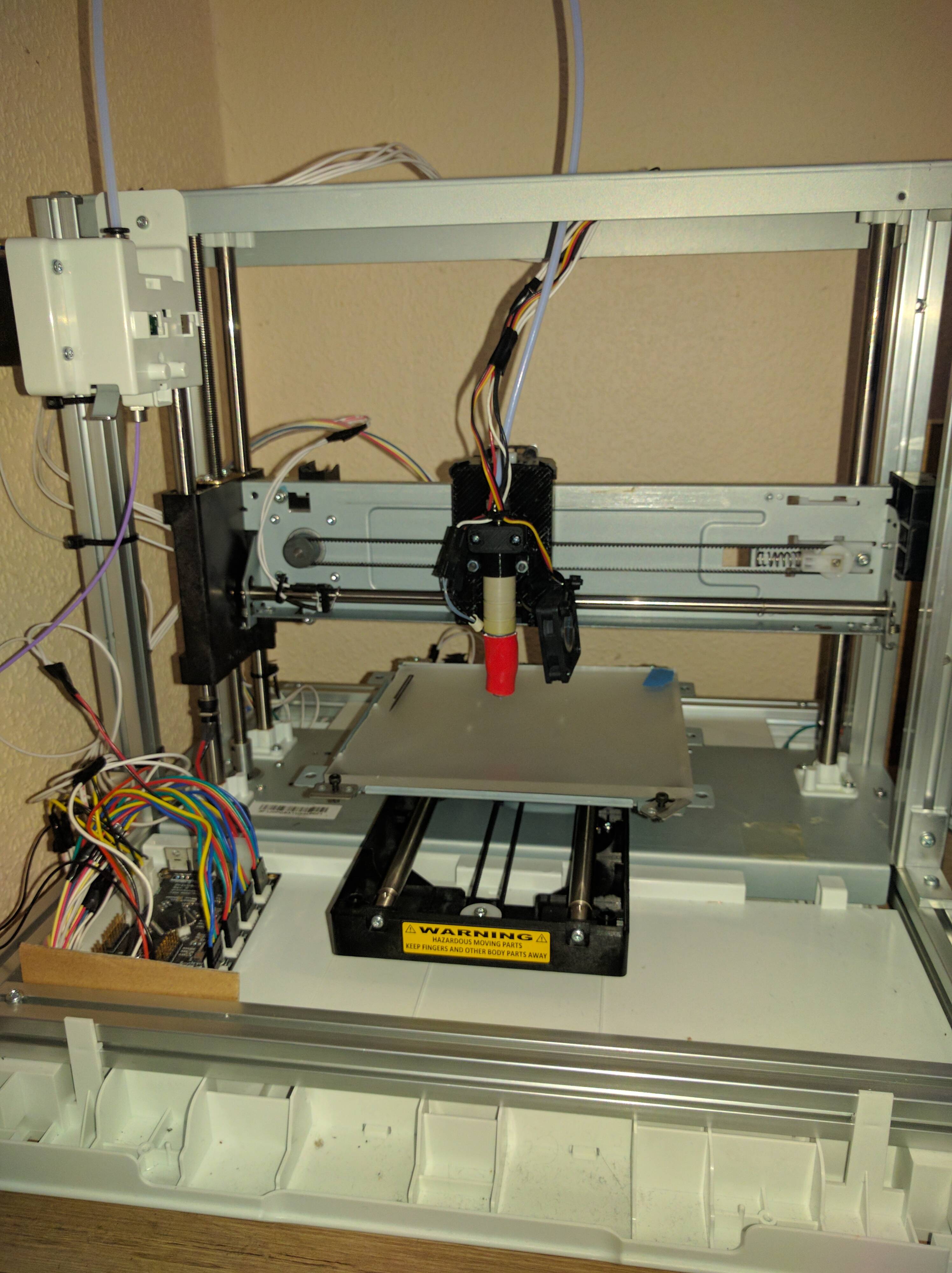
Pretty good I'd say. I have yet to print a case of any sort for my RAMPS board, so it's just sticking bare out of the side of the Jr's case with a bunch of wires, but the way I hooked it up you can have all the original parts of the case reattached and enclosed (all my cables come through the rectangular hole where the original power on/off switch was). Having the full case intact and enclosed is important to me for noise reduction purposes. I did not drill or cut any part of the case. I simply removed the stock controller board.
Part 2: Demolition
But you said...
Yes, I'm kidding. You won't be destroying anything in this part (not intentionally at least). But you will be taking some things apart, removing some items, and changing a little bit about how the Jr is built.
Unplugging
First off, unplug your machine. While it's true there's no high voltage or anything running through it, it's safer for you (and the electronics) to unplug and ground yourself before opening anything up or touching any contacts or wires.
Uncasing
You want to get as much access to the inside of your system as possible. To do this you'll want to remove the top and sides and some other things that'll get in the way:
Look at the back of the machine. Remove the two screws at the top, which hold the top panel in place.
Slide the top panel toward the back of the machine. After a few inches the ears will be clear and you can simply lift it off.
At the top of the frame, find the two sets of two bolts holding the top of the sides in place. They are each spanned by a plastic strap with rubber and metal washers. Remove these four bolts and the straps.
Flip the machine on its back (or upside down). The sides are held at the bottom with two clips each, one near the front and one near the back of the unit. Use a flathead screwdriver or other levering tool to push the two clips down and outward slightly (as soon as the ridge of the clip clears the slot, you're good).
Gently pry the bottom edge of the side panels away from the frame. I found that prying from the top of the panel as well helps angle the clips away from their catch so they can pop out. A little bit of gentle force may be required here. Mine tended to pop out suddenly after prying from the top, but no harm was done to the clips.
Optionally (I did not do this), flip the unit upright again, open the front cover, and find the screws that hold the front hinges to the frame. Unscrew these and remove the front panel. This can make it easier to move and handle the box, but again, it's optional.
Now that the case is mostly off, there are some other items you'll want to remove to access the parts you need:
Unscrew the two torx screws holding the front LCD panel on. Once loose, flip it forward and pull the two ribbon cables from their sockets. There are no clips, they just pull out. Set the LCD panel aside (you will no longer need it).
On the left side of the system, you'll see the NFC reader at the back of the filament holder. Two screws hold this in. Unscrew them, disconnect the 6-pin JST connector, and then remove the NFC reader. Its antenna card is slid inside the filament holder; remove this as well. (I have not confirmed this, but it may be possible to use a Raspberry Pi or Arduino to interface with this NFC reader for other projects. I'd like to hear about it if anyone has tried.)
Use your hex driver (or Allen wrench) to unscrew the two bolts that hold the filament holder to the frame. Make sure you recover the two nuts that will now be loose inside the V-slot frame. You can either set this holder aside, or reinstall it later at your option. It won't fit most spools other than XYZ branded filament anyway. I reinstalled mine post-conversion since I still have quite a lot of XYZ filament.
Decabling
Now that those are out of the way, we'll be dealing with the cables and controller board.
With the unit still upright, go ahead and disconnect the flex cable that plugs into the extruder (unclip the extruder unit if needed). There are two latches on either side of the cable. Pinch them and pull the cable out. We will not be reusing this flex cable.
Go ahead and pull the extruder flex cable out of the unit, making sure to unclip it from the right side of the X gantry. Some force may be required to get it unstuck as the adhesive used here is quite strong, so (if you care) be careful not to damage it, particularly where it's folded into the 90-degree bend. Loosen it up to the point where the flex cable dives into the floor of the unit
Flip the unit on its back again. There are two panels we need to remove
On the floor of the unit where the filament holder used to be, there's a small hatch that lets you access the internal cabling. Find the two clips on the bottom of the unit and push them in and up to remove this hatch from the inside.
Remove the two screws that hold the bottom panel on. Remove the bottom panel to expose the controller board.
All Aboard
OK, now that we have access to the board, let's talk a little bit about what we see here, and what we'll be doing.
Image courtesy of graepfruit4 (OK, I lifted it) via http://www.soliforum.com/post/108847/#p108847:
What you're looking at is the Atmel ATSAM48E8-based microcontroller board that runs the Da Vinci Jr firmware, and a bunch of connectors. The system here is virtually equivalent to what your RAMPS or equivalent microcontroller board provides, just repackaged as a single proprietary PCB with unknown pins operating the various components.
If you're so inclined, it's possible to wipe your firmware by jumping the solder pads labeled "SW2" just to the left of the microcontroller chip (jump it, power on for 30 seconds, power off, remove the jumper, power on again). The system will enter "Bootloader" mode, and at this point you can connect to it via USB to reprogram it yourself (maybe someone wants to figure out how to make Repetier work, eh?) ![]()
The colors of the various connectors may vary depending on the specific hardware revision and/or place of manufacture, but the positions should be the same on the board.
Starting from the top left and going right and down, the various connections are:
Ground wire (red wire bolted to board)
Big, wide flex cable: Hot end heater, thermistor, heatbreak fan
SD Card flex cable
LCD flex cable
Ground wire (green wire bolted to board)
80mm case fan (Labeled "Reflow fan", 2 pins)
NFC reader (6 pins)
LED light bar (labeled "TopLamp", 3 pins)
Extruder stepper ("Motor-E1")
Optical endstops (2x6 pin connector, 3 pins per endstop). As shown in this photo (looking from the back of the connector), the three X axis wires are on the top left, Y is on the bottom left, and Z is on the bottom right. The other three pins are unused. For each set of three pins (again, as shown in this image from the back of the connector), left-to-right they are: 5v+, Ground, Signal. USE CAUTION as the endstops in the Jr do not have internal resistors. YOU MUST add power and pull-up resistors before connecting them to the RAMPS board (thanks for this information go to grimjack via http://www.soliforum.com/topic/13074/te … avicni-jr/)
Z-axis extruder stepper ("Motor-Z")
Y-axis extruder stepper ("Motor-Y")
X-axis extruder stepper ("Motor-X")
Filament sensor ("Pull Filament"). As noted before, I haven't attempted to hook this up or figure out the pinout for this connector.
OK, now that we've gone through that, rip'em all out! Disconnect the ground wires, the steppers, the endstops, everything. Pinch the clip on the extruder flex cable and remove that. The LCD and SD cables just pull straight out again. Fish the extruder flex cable through the unit and remove it entirely (it's really very long and will get in the way). Remove the SD and LCD flex cables if you wish, but I've left mine in for now since they're adhered to the chassis a long way under the Y carriage, and they don't really get in the way of anything.
Now remove the six screws that hold the board in and set the board aside. We won't be needing it anymore. This opens up the holes on the side of the unit where the power jack, USB cable and on/off switch used to be. We'll be using these holes later.
Rerouting
Flip the unit upright again now that you have access to the routing of the cables through the chassis.
Use a screwdriver or other levering tool to unclip the two wire harnesses under the hatch in the floor of the unit
Remove the 6-pin NFC cable entirely
Reroute the other cables as necessary to get as much length out through the bottom of the unit into the controller board compartment.
You can optionally replace the cable hatch now, or do it later when re-assembling.
Part 3: Connecting Up
Now you're going to make good use of that ribbon cable, the connector kits and crimper that I listed in the parts list above. But first, you'll want to set up your RAMPS firmware so that you have a platform to test with.
Powering-on and Flashing
Before connecting anything electrically to your Jr, I recommend setting up and flashing Marlin on your RAMPS 1.4 board. This is to ensure that you have a method of testing the operability of the various components you're hooking up one-by-one. Your RAMPS vendor probably gave you instructions to follow, as certain settings vary between different LCD boards and rotary encoder (or other input methods). Follow those instructions first, using the information here for reference. You can find the official RAMPS 1.4 discussion of the Marlin firmware here: http://reprap.org/wiki/Marlin.
In my case, I had a female power jack lying around that happened to be compatible with the stock Jr power adapter. I soldered some wire onto this and used this for my 12V+ power supply. If you purchased an external power supply, hook it up per the standard instructions. If you need to wait on the 12V power supply for some reason, you can still flash your board using power over USB.
I have customized my Marlin firmware for the Da Vinci Jr and my RepRap Full Graphic 12864 LCD with rotary encoder, and set it up to work with stock hardware. You can get my settings from my fork of the Marlin repository, here:
https://gitlab.com/anthem/Marlin
This includes my determined values for the stepper values, my fine-tuned value (88 steps) for extrusion, which may or may not be best for your hardware, and updated values for my particular rotary encoder. These settings also assume that you want AUTO_FAN handling, turning on both the heatbreak and case fans using pin D9 when the hot end is over 50 degrees Celsius.
In my case, I set up the Arduino SDK per vendor instructions on a Raspberry Pi that is connected to the RAMPS board full-time. That part is totally optional.
Making Cables
We're going to need to make quite a few cables. It can be a good idea to use jumpers and a breadboard to prototype and test the connections before committing the effort and resources into making the cables. You can run the RAMPS system using only suitable jumpers if you wish, but it will be a messier and likely more error-prone setup.
To make a cable, tear away pieces of the ribbon cable to get the number of conductors you need for each, then cut them to length (think ahead to make good use of the cable -- there should be plenty, but I'd hate for someone to make too many cuts and run out prematurely). I find that the wire cutters on standard needlenose pliers work well for stripping several wires on the ribbon cable at once, but if you have a dedicated stripper or another preferred method, of course use what you prefer.
Measure each length of cable based on how far you want the cable to extend out the bottom of the unit. Make sure to leave enough slack to maneuver your RAMPS board (and maybe mount it in a case to the side of the unit -- up to you).
Precautions
I recommend that you skip back and forth through these instructions as necessary, testing only one component at a time. Use a multi-meter to check any assumptions about voltages or resistances before committing to anything.
ALWAYS turn off power before changing any connections! It's too easy to make mistakes or slip-ups which can end up destroying components. Electricity is instant and unforgiving.
Make sure that you never attempt to turn on a stepper without the stepper actually connected, as it can destroy the stepper driver (best to remove them from the RAMPS board until you're ready to hook them up in fact).
Also do not attempt to hook up the optical endstops until you have read the section below concerning those. You need to add resistors or you will blow up the IR LED, the detector, or both.
Otherwise, follow good electrical common sense.
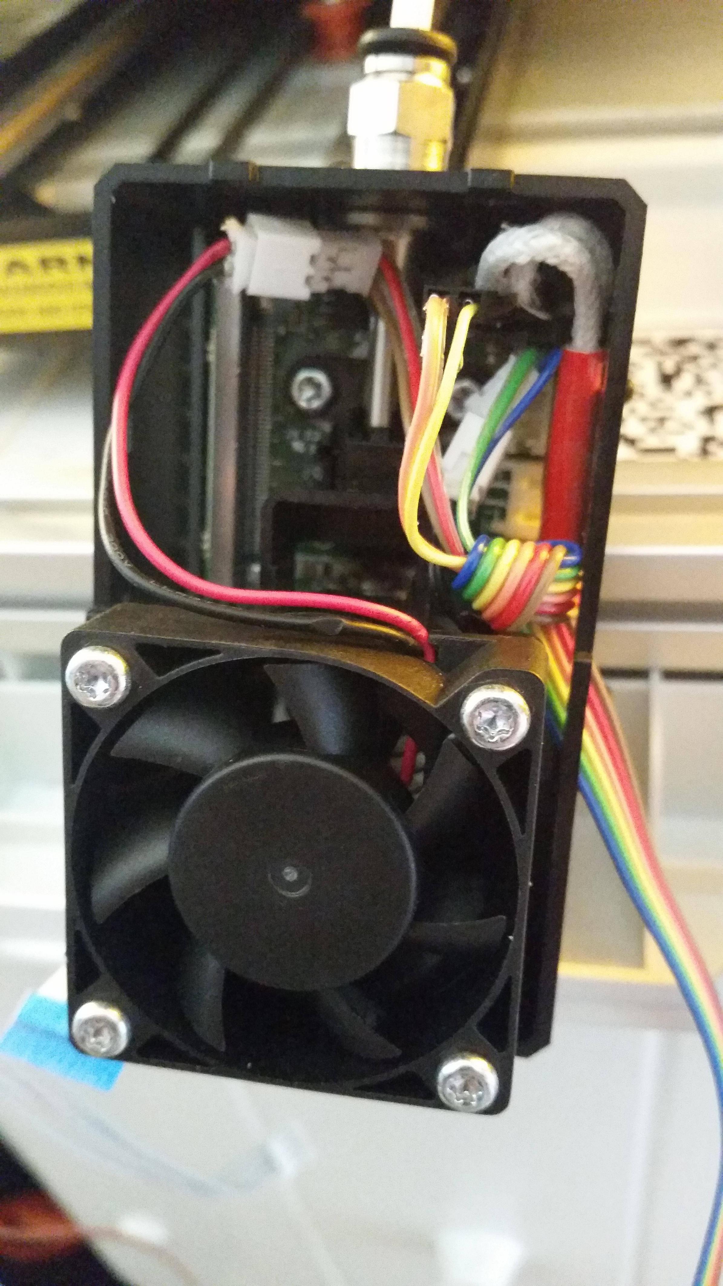
Hot end, thermistor and heatbreak fan
We'll start with the big one. Tear off a good length (I recommend about 3 feet) of ribbon cable with either 6 or 8 conductors (I used 6, but if you're concerned about resistive heating or are using a custom higher-wattage hot end, use 8 conductors, doubling-up the wires for the hotend).
Make this cable as follows:
Split the ribbon cable into three sets of two wires (or two sets of two plus one set of four if you're doubling up for the hot end)
Crimp one 2.0mm JST female connector to the set of wires for the thermistor
Crimp another 2.0mm JST female connector to the set of wires for the fan. Pay attention to polarity here (at least make note of what color you're using; I ended up using red and brown, matching red to positive). This is VERY important. If you destroy this fan, it'll be difficult to find a similar replacement.
Crimp a 2.54 *male* dupont connector to the wires for the hotend. Polarity doesn't matter here.
Now for the other end. Crimp a 2.54mm Dupont female connector on the other end of the thermistor wires. The other pairs for the fan and the hot end will be left bare (stripped).
Connect it up (see photo below):
Remove the extruder from the X gantry
Grab both sides of the extruder cover (at around fan level), pinch hard and pull to remove the cover
Remove the four screws holding the fan on
Remove the two screws holding on the fan shroud (may not be necessary, depends on how easily you're able to get to the connectors)
Disconnect the stock JST connectors for both the fan and the thermistor. You'll probably need to use needlenose pliers to remove the thermistor connector without damaging it.
Insert each of the JST connectors into a male JST housing from the kit. This is not an ideal (as in secure) connection, but I was unable to find male 2.0mm JST crimp connectors, so this is the best I could do. You might want to wrap a piece of electrical tape around the connection once it's been tested to keep it from pulling out accidentally.
Insert the pins of the male housings into the fan and thermistor connectors. Make sure you get the fan polarity right.
The connector for the hot end is soldered into the extruder board. Use the male dupont connector and insert the pins into the back of the connector on the board, shoving them up next to the wires inside the connector. Use an ohmmeter between your connector pins and the solder points on the board to ensure you have a good connection here. There are solder points at both the side and bottom of the hotend mount. One wire goes to the side points, the other wire goes to the bottom points.
Once inserted, bend the connector downward so that there's clearance for the cover can go back on
Tie a loose overhand knot in the ribbon cable inside the extruder housing for strain relief
Insert the RAMPS end of the cable through the long slot in the extruder housing at the right (the Dupont connector should fit through)
Route the ribbon cable to the right of the machine, hook it into the clip in the X gantry and down the side of the machine. Slip it through the hole the old flex cable used to go through, then fish it out the bottom and out through the hole where the power switch was. Make sure you leave enough slack inside the machine for when the extruder is X home and Z maximum.
Insert the hot end wires into the D10 screw terminals. Polarity doesn't matter.
Insert the fan connectors into the D9 screw terminals. Make sure you get the polarity right (if you're unsure, put an ohmmeter on it at the highest resistance -- if you read anything other than a closed loop, then the wire you have your positive lead on should go into the positive power terminal).
Plug the thermistor Dupont connector into the thermistor pins on the RAMPS board (refer to RAMPS documentation for this).
Reassemble in reverse order: fan shroud, fan, extruder cover (though you might want to jump ahead and test the components first -- just make sure not to run the nozzle for long without the fan present and working or you'll get a clogged extruder). Note that the stock fan is oriented to blow outward, sucking air from the back of the unit across the heatbreak and out toward the front (thanks kr15_uk for making a note of that).
Test it:
Double-check that you have all the connections right as above
Plug in your RAMPS board to the 12V source.
You should see a non-zero nozzle temperature reading. If it errors out with MINTEMP that means you have an open circuit on your thermistor, so unplug the board and check those connections.
Test the fan. Use the input on your board to go to Control > Temperature > Fan and set it to 255 (full blast -- there's no PWM here, just on/off; if you select something less the fan may not spin). The fan should spin. If it doesn't, check your fan connection. If it bursts into smoke like mine did, unplug the board and go find yourself a replacement 40x40x10mm fan
 The stock fan is 11.4cfm, but you'll probably have a hard time finding that through any consumer source. I'm making do with a 6.3cfm with a 9 cfm on order. That does the job but it isn't ideal.
Turn off the fan
On the RAMPS board, go to Control > Temperature > Nozzle and set the nozzle to some low-ish temperature, say 100 Celsius. Exit back to the main screen and make sure the temperature climbs reasonably well. If you haven't reinstalled your fan at this point, turn the temperature back down before it gets too high to avoid damaging your hot end. If you're using the configuration I provided, the fan should automatically kick on when the nozzle hits 50 Celsius.
Case Fan
This is an easy one.
Make a 2-wire cable using a 2.0mm JST on one end, and bare wire on the other end.
Plug the JST into the 2-pin fan connector under the machine using a male JST housing (and optionally tape it)
Route it through the power switch hole and to the RAMPS board
Remove the heatbreak fan wires from the screw terminal, twist those wires together (and optionally solder or crimp them with a pin) and insert them back into D9. Make sure you get bothpolarities correct. Check before twisting the wires with an ohmmeter if necessary.
Test using the fan procedure above (Control > Temperature > Fan: 255). Both fans should start up and run. Then turn the fans off.
A note on fans
Some of you might have extra part cooling fans installed. If that's the case, you'll need to do some configuration in the Marlin files to reassign some pins so that you have D9 set aside for the stock fans, and D8 for your part fans (or some other reasonable configuration -- this gets trickier if you have installed a heated bed for which D8 is the default). I'm not an expert on this, so refer to the RAMPS/Marlin documentation for this kind of configuration.
Steppers
All the steppers are treated the same way and are easy to connect using a straight cable. I found that adjacent pairs of wires on the Jr's connectors make the stepper pairs. An easy way to check this is to insert a wire or jumper into the connector to short the pair, then try to manually move the stepper -- if it becomes hard to move and "clunky", you've found a pair.
For each stepper (there are four: X, Y, Z and extruder):
Tear off a 4-wire strip from the ribbon cable. The stock cables for each stepper are different lengths because they're made to just reach the connector on the board. Measure each individually or just leave a lot of slack.
Strip and crimp a 4-pin JST female connector on one end
Strip and crimp a 4-pin Dupont female connector on the other end
Plug the cable to the stepper connector using JST male housing (and optionally tape it). If you accidentally reverse the connector, the stepper will run backward, so just reverse the Dupont connector on the RAMPS board.
Test the steppers. For each stepper (X, Y, Z and Extruder):
Manually move the stepper to a middle position (so that you don't "crash" if you move in the wrong direction)
On your RAMPS, go to Prepare > Move Axis > 1 mm > X/Y/Z/Extruder. If you don't see the extruder as an option here, you need to unset Marlin's PREVENT_DANGEROUS_EXTRUDE setting temporarily.
Move the motor in the positive direction. For X, it should move right. For Y, it should move forward, and for Z it should move up. The extruder stepper should extrude (push filament toward the hot end) for positive, and retract for negative.
Since you don't have the optical sensors hooked up, the RAMPS board will prevent moving a stepper in a negative direction at this point (to avoid a crash). This is normal. But if you see an axis actually move in a negative direction, then this means you need to reverse your connector for that axis.
Optical Sensors
These are the most complicated cables to make. I opted to crimp the needed resistors inline with the connectors (on the RAMPS side of the cable). You can do it a different way if you'd like, including jumping the connector out to a breadboard, or even making your own PCB. If you have your own way to do this, please share.
Also, I was unable to source a 2x6 (12 pin) connector housing to use. If you have access to one, please use it. My solution described below will work, but it's a pain to make correctly.
First, get your parts together:
3x 12 KOhm resistors (you can resort to 10k if it's what you have on hand)
3x 220 Ohm resistors
3x 2.0mm JST connectors (with pins)
3x 2.54mm 3-pin Dupont connectors (with pins)
3x 2.54mm 1-pin Dupont connectors (with pins)
3x 2.0mm JST male housings (you are going to modify these later)
Tear off three lengths of ribbon cable. They should be about the same length since all the endstops share one stock connector.
When looking at the 12-pin endstop connector from the front (I mean the side with the holes, rather than the back where the wires enter the connector), position the unused pins at the bottom right. Then the X endstop is on the bottom left, Y is on the top left, and Z is on the top right. [TODO: Diagram]
In each of these three sets of three pins, the rightmost pin is 5V+, center is Ground, and the leftmost pin is Signal. We are going to need to put a 220 Ohm resistor on the 5V+ connector, and the 12k resistor between 5V+ and Signal as a pull-up resistor.
Make the cables as follows. You are going to crimp both resistors and wires into some of the pins. DO NOT crimp the JST connectors just yet (we'll do that later).
Strip all your cables as normal
If your resistors have long leads, trim them to be a bit shorter (just long enough to fit through your crimper and securely into a Dupont pin without crushing the resistor with the crimper)
Prepare a Dupont pin in your crimper, and insert one end of both the 220 Ohm and the 12K resistors into the pin, then crimp them together
Prepare another Dupont pin, and insert the Signal wire and the other end of the 12K resistor into this one. Crimp.
Prepare another Dupont pin, and insert only the Ground wire into this one. Crimp.
At this stage, you have your three pins to insert into the 3-pin Dupont connector, with your 5V+ wire hanging free. Insert the three pins into the 3-pin housing. Make sure you get the order right: 5V+ (two resistors), Ground, Signal.
Trim the 5V+ wire that's still hanging free a bit and strip it again. You want to shorten it just enough that it can still be crimped into a pin that will go into a single-pin housing which will plug into the free end of the 220Ohm resistor.
Crimp the 5V+ wire into a Dupont pin. Insert it into the single-pin housing.
Plug the free end of the 220 Ohm resistor into the single-pin housing.
Repeat the above process for all three endstop cables. Make sure you never apply full current across the endstop, as the stock endstops DO NOT have on-board resistors and you will definitely blow either the LED or the detector. I accidentally blew one of these while prototyping (I got complacent and didn't double-check my wiring). I'll tell my story of how I repaired it in another post. Don't do that.
Now that you have your cables, plug them into the X-min, Y-min and Z-min endstop slots on the RAMPS board. Make sure that the Signal wire is at the top of the board (closest to the edge) and 5V+ is at the bottom (closest to the middle). Ground is the center pin. If you accidentally get this wrong, it shouldn't blow your endstop, but you'll see some weird results.
Now the weird part -- plugging it into the 12-pin connector. You can either use jumpers to break out the connector into the individual endstop cables, or do like I did and modify some JST male housings:
Set a male housing with the "slot" side down on a working surface and use a hobby knife to cut off the rightmost wall of the connector, plus a little extra. You want the edge of the housing that's left to be as close to 1mm as possible (half the distance between two 2.0mm pins). This will be for your Y endstop.
Rotate the same housing and cut off the wall that has the "slot" in it, again aiming for 1mm remaining material.
Insert this housing into the top left (Y) pins with the cut sides at the right and bottom.
On another male housing, cut off just the slotted side. This will be for your X endstop.
Insert it into the bottom left set of pins with the cut side up
Take your third housing and cut off just the left side, with the slot facing down. This is for Z endstop.
Insert the housing into the Z pins (top right) with the cut side facing left.
[TODO: Photo of 12-pin hack job]
Finally, you can crimp the three JST connectors on the other end of your cables. For each of the three cables:
Match up the wire role/polarity with the pin on the 12-pin connector, and figure out which way to orient the connector to match the modified housings. Per the directions above, with the "slot/nub" side of the connector facing down and holes facing you, 5V+ will be on the left of the Y-axis and Z-axis connectors, but on the right of the X-axis connector.
Crimp the JST connector for the three wires and insert the pins to match the orientation you worked out above.
Insert the connectors into the modified housings, respecting the orientation (per the directions above, this means that the "nub" will always be facing the center of the connector).
Testing (repeat for each axis):
Move the extruder/Y carriage/Z axis to a position other than home so that the endstop is open.
Use your voltmeter to check the voltage across the 5V+ and Ground wires. This should be a low voltage (~1V) indicating the voltage across the LED.
Check the voltage across Ground and Signal. This should be a very low (almost zero) voltage with the endstop open.
Close the endstop, either by moving the axis or physically blocking the path between the emitter and detector (for the Z axis, setting an an SD card in the endstop slot is easier than twisting the threaded rod). You should now read 5V across Ground and Signal.
If you don't get 5V with the endstop closed, check your connections. Make sure you haven't inserted the connector backward. Make sure you didn't mix up your endstop axes.
Light Bar
The light bar is a 3-connector 12V switched LED circuit. One wire is 12V+, one Ground, and the other is a 5V signal that controls the brightness of the lights. When looking at the stock connector, holes facing you and "nub" down, 12V+ is on the right, Ground in the center and Signal on the left.
To make the cable and connect up:
Crimp a 3-pin JST on the one end and connect it with a male housing and tape.
On the other end, crimp a single (1-pin) Dupont connector on the switch wire, leaving the other two wires bare.
Connect the 12V+ wire to a 12V pole of the screw terminal power connector of the RAMPS board (you could also attach this to one of your positive terminals of D8/9/10)
Connect the Ground wire to a ground pole of the screw terminal power connector.
Crimp a 10 or 12K resistor into a Dupont pin and insert it into another single-pin connector.
Plug the single-pin connector with resistor into the D4 pin of the RAMPS board, then plug the single-pin connector of the signal wire into the other resistor lead.
Testing:
With your RAMPS board fired up, issue the gcode "M42 P4 S255", which means "Turn on pin 4 full". Let there be light!
If it doesn't light, check that you haven't reversed a connection. The light bar seems to have basic polarity protection so it shouldn't be too easy to destroy if you're basically careful.
If it lights, but only dimly, make sure you haven't reversed your signal and 12V connections (turn the connector around)
Part 4: Configuration and Calibration
If you used the Marlin configs I provided, and the same RAMPS board as me, your Da Vinci Jr should already be somewhat dialed-in. I've set the stepper values already, and assuming your machine is similar enough to mine, I've also set up the default HOME_POS and MAX_POS values so that your extruder knows how far it can go.
The one most important setting that you must check yourself is your Z-offset. In Marlin this is determined by the HOME_POS settings, and can be fine-tuned in EEPROM settings using the M206 command.
So other than possibly fine-tuning your extrusion steps you should be set to go.
I followed Triffid Hunter's Calibration Guide to set my initial values: http://reprap.org/wiki/Triffid_Hunter&# … tion_Guide
To set your Z-offset, I recommend the following reading: http://airtripper.com/1799/marlin-firmw … code-m206/
[TODO: Talk about the specific values I set in the Marlin configs and how I arrived at them]
Part 5: Cleaning up
At this point, congratulations! You have successfully completed converting your printer to RAMPS 1.4. Enjoy the new-found freedom.
You'll probably want to put things back together now and take care of some final touches:
It's probably a good idea to connect a wire from the Ground terminal of your RAMPS board and screw it to the shielding plate in the controller compartment, then re-connect the stock ground wires.
Replace the controller compartment cover.
If you didn't in a previous step, replace the clip-in cover inside the unit that hides the cable routing
Use a piece of tape or some other adhesive to keep the extruder ribbon cable in place, both where it clips to the X gantry at the far right, and where it goes through the bottom of the unit to keep it from slipping and losing slack.
(Optional) Replace the filament holder. Probably only useful if you still use XYZ filament, otherwise go print yourself a new one!
(Optional) Replace the front and side covers. If you care about it, having the covers on definitely reduces the noise from the fans.
(Optional) Replace the LCD screen. Only desirable if you want to plug the front hole for noise purposes, otherwise just leave it off since it won't function anyway.
(Optional) Figure out how to wire up and configure the filament sensor, and post your instructions here!
Part 6: The Many Ways I Screwed Up and Broke Stuff but Made it Work Anyways
To do. ![]()
To be continued...