51 (edited by carl_m1968 2015-09-22 06:34:35)

Re: Extruder 1 and 2 do not spin - Repetier Firmware

EMC2 Robo wrote:

Hello everyone,

Marlin Firmware Update:
- Extruder #1 heater is working (No errors... woohoo)
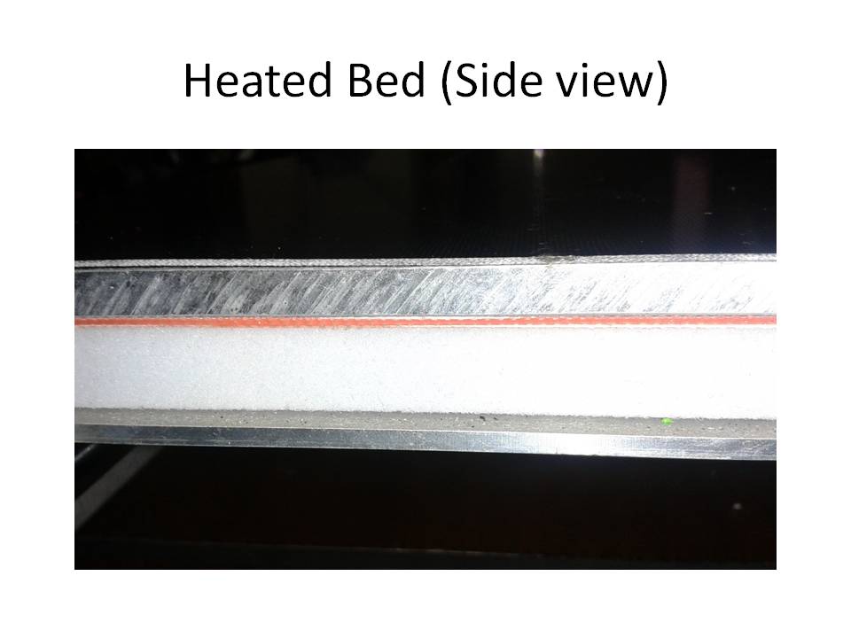
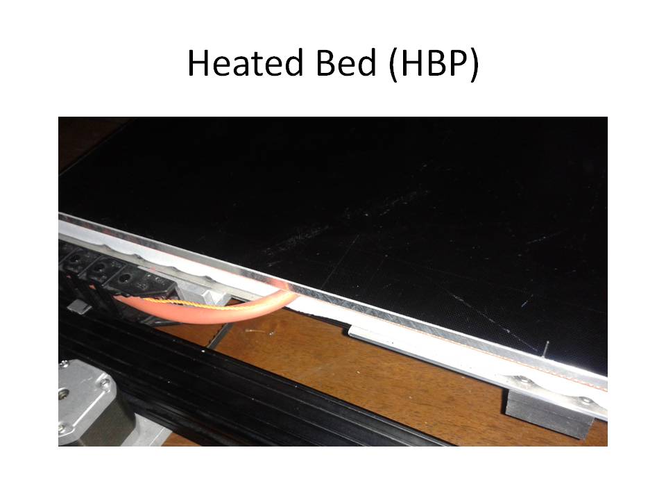
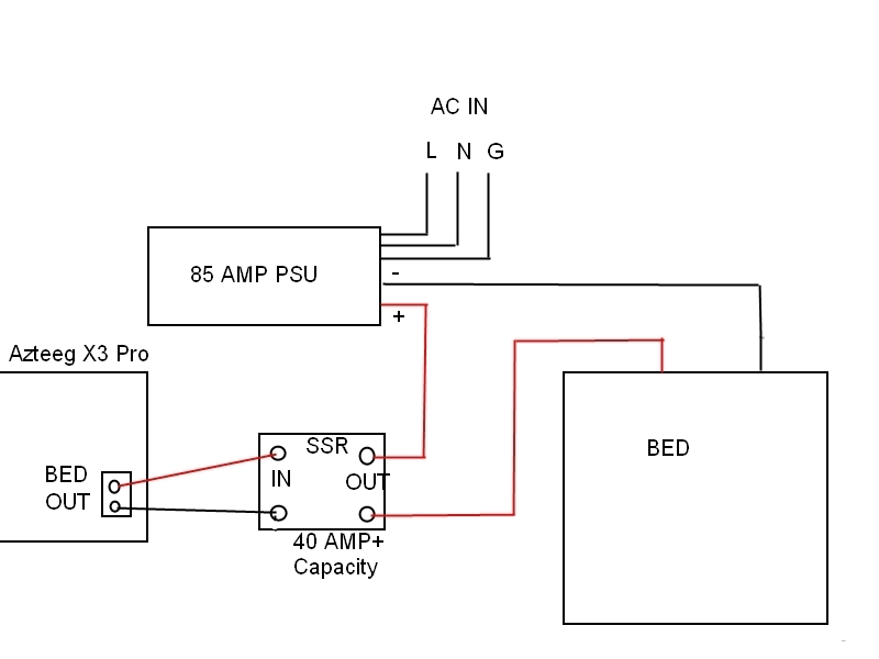
- Heated Bed not working ( I do not receive an error message, it just does not warm up at all.

Any ideas what I can do to fix heated bed?

configuration.h file

#ifndef CONFIGURATION_H
#define CONFIGURATION_H

// This configuration file contains the basic settings.
// Advanced settings can be found in Configuration_adv.h
// BASIC SETTINGS: select your board type, temperature sensor type, axis scaling, and endstop configuration

//===========================================================================
//============================= DELTA Printer ===============================
//===========================================================================
// For a Delta printer replace the configuration files with the files in the
// example_configurations/delta directory.
//

//===========================================================================
//============================= SCARA Printer ===============================
//===========================================================================
// For a Delta printer replace the configuration files with the files in the
// example_configurations/SCARA directory.
//

// User-specified version info of this build to display in [Pronterface, etc] terminal window during
// startup. Implementation of an idea by Prof Braino to inform user that any changes made to this
// build by the user have been successfully uploaded into firmware.
#define STRING_VERSION_CONFIG_H __DATE__ " " __TIME__ // build date and time
#define STRING_CONFIG_H_AUTHOR "(none, default config)" // Who made the changes.

// SERIAL_PORT selects which serial port should be used for communication with the host.
// This allows the connection of wireless adapters (for instance) to non-default port pins.
// Serial port 0 is still used by the Arduino bootloader regardless of this setting.
#define SERIAL_PORT 0

// This determines the communication speed of the printer
#define BAUDRATE 250000

// This enables the serial port associated to the Bluetooth interface
//#define BTENABLED              // Enable BT interface on AT90USB devices


//// The following define selects which electronics board you have. Please choose the one that matches your setup
// 10 = Gen7 custom (Alfons3 Version) "https://github.com/Alfons3/Generation_7_Electronics"
// 11 = Gen7 v1.1, v1.2 = 11
// 12 = Gen7 v1.3
// 13 = Gen7 v1.4
// 2  = Cheaptronic v1.0
// 20 = Sethi 3D_1
// 3  = MEGA/RAMPS up to 1.2 = 3
// 33 = RAMPS 1.3 / 1.4 (Power outputs: Extruder, Fan, Bed)
// 34 = RAMPS 1.3 / 1.4 (Power outputs: Extruder0, Extruder1, Bed)
// 35 = RAMPS 1.3 / 1.4 (Power outputs: Extruder, Fan, Fan)
// 4  = Duemilanove w/ ATMega328P pin assignment
// 5  = Gen6
// 51 = Gen6 deluxe
// 6  = Sanguinololu < 1.2
// 62 = Sanguinololu 1.2 and above
// 63 = Melzi
// 64 = STB V1.1
// 65 = Azteeg X1
// 66 = Melzi with ATmega1284 (MaKr3d version)
// 67 = Azteeg X3
// 68 = Azteeg X3 Pro
// 7  = Ultimaker
// 71 = Ultimaker (Older electronics. Pre 1.5.4. This is rare)
// 72 = Ultimainboard 2.x (Uses TEMP_SENSOR 20)
// 77 = 3Drag Controller
// 8  = Teensylu
// 80 = Rumba
// 81 = Printrboard (AT90USB1286)
// 82 = Brainwave (AT90USB646)
// 83 = SAV Mk-I (AT90USB1286)
// 84 = Teensy++2.0 (AT90USB1286) // CLI compile: DEFINES=AT90USBxx_TEENSYPP_ASSIGNMENTS HARDWARE_MOTHERBOARD=84  make
// 9  = Gen3+
// 70 = Megatronics
// 701= Megatronics v2.0
// 702= Minitronics v1.0
// 90 = Alpha OMCA board
// 91 = Final OMCA board
// 301= Rambo
// 21 = Elefu Ra Board (v3)
// 88 = 5DPrint D8 Driver Board
// 999 = Leapfrog

#ifndef MOTHERBOARD
#define MOTHERBOARD 68
#endif

// Define this to set a custom name for your generic Mendel,
// #define CUSTOM_MENDEL_NAME "This Mendel"

// Define this to set a unique identifier for this printer, (Used by some programs to differentiate between machines)
// You can use an online service to generate a random UUID. (eg http://www.uuidgenerator.net/version4)
// #define MACHINE_UUID "00000000-0000-0000-0000-000000000000"

// This defines the number of extruders
#define EXTRUDERS 1

//// The following define selects which power supply you have. Please choose the one that matches your setup
// 1 = ATX
// 2 = X-Box 360 203Watts (the blue wire connected to PS_ON and the red wire to VCC)

#define POWER_SUPPLY 1

// Define this to have the electronics keep the power supply off on startup. If you don't know what this is leave it.
// #define PS_DEFAULT_OFF

//===========================================================================
//=============================Thermal Settings  ============================
//===========================================================================
//
//--NORMAL IS 4.7kohm PULLUP!-- 1kohm pullup can be used on hotend sensor, using correct resistor and table
//
//// Temperature sensor settings:
// -2 is thermocouple with MAX6675 (only for sensor 0)
// -1 is thermocouple with AD595
// 0 is not used
// 1 is 100k thermistor - best choice for EPCOS 100k (4.7k pullup)
// 2 is 200k thermistor - ATC Semitec 204GT-2 (4.7k pullup)
// 3 is Mendel-parts thermistor (4.7k pullup)
// 4 is 10k thermistor !! do not use it for a hotend. It gives bad resolution at high temp. !!
// 5 is 100K thermistor - ATC Semitec 104GT-2 (Used in ParCan & J-Head) (4.7k pullup)
// 6 is 100k EPCOS - Not as accurate as table 1 (created using a fluke thermocouple) (4.7k pullup)
// 7 is 100k Honeywell thermistor 135-104LAG-J01 (4.7k pullup)
// 71 is 100k Honeywell thermistor 135-104LAF-J01 (4.7k pullup)
// 8 is 100k 0603 SMD Vishay NTCS0603E3104FXT (4.7k pullup)
// 9 is 100k GE Sensing AL03006-58.2K-97-G1 (4.7k pullup)
// 10 is 100k RS thermistor 198-961 (4.7k pullup)
// 11 is 100k beta 3950 1% thermistor (4.7k pullup)
// 12 is 100k 0603 SMD Vishay NTCS0603E3104FXT (4.7k pullup) (calibrated for Makibox hot bed)
// 20 is the PT100 circuit found in the Ultimainboard V2.x
// 60 is 100k Maker's Tool Works Kapton Bed Thermistor beta=3950
//
//    1k ohm pullup tables - This is not normal, you would have to have changed out your 4.7k for 1k
//                          (but gives greater accuracy and more stable PID)
// 51 is 100k thermistor - EPCOS (1k pullup)
// 52 is 200k thermistor - ATC Semitec 204GT-2 (1k pullup)
// 55 is 100k thermistor - ATC Semitec 104GT-2 (Used in ParCan & J-Head) (1k pullup)
//
// 1047 is Pt1000 with 4k7 pullup
// 1010 is Pt1000 with 1k pullup (non standard)
// 147 is Pt100 with 4k7 pullup
// 110 is Pt100 with 1k pullup (non standard)

#define TEMP_SENSOR_0 -1
#define TEMP_SENSOR_1 -1
#define TEMP_SENSOR_2 0
#define TEMP_SENSOR_BED 2

// This makes temp sensor 1 a redundant sensor for sensor 0. If the temperatures difference between these sensors is to high the print will be aborted.
//#define TEMP_SENSOR_1_AS_REDUNDANT
#define MAX_REDUNDANT_TEMP_SENSOR_DIFF 10

// Actual temperature must be close to target for this long before M109 returns success
#define TEMP_RESIDENCY_TIME 10  // (seconds)
#define TEMP_HYSTERESIS 3       // (degC) range of +/- temperatures considered "close" to the target one
#define TEMP_WINDOW     1       // (degC) Window around target to start the residency timer x degC early.

// The minimal temperature defines the temperature below which the heater will not be enabled It is used
// to check that the wiring to the thermistor is not broken.
// Otherwise this would lead to the heater being powered on all the time.
#define HEATER_0_MINTEMP 5
#define HEATER_1_MINTEMP 5
#define HEATER_2_MINTEMP 5
#define BED_MINTEMP 5

// When temperature exceeds max temp, your heater will be switched off.
// This feature exists to protect your hotend from overheating accidentally, but *NOT* from thermistor short/failure!
// You should use MINTEMP for thermistor short/failure protection.
#define HEATER_0_MAXTEMP 275
#define HEATER_1_MAXTEMP 275
#define HEATER_2_MAXTEMP 275
#define BED_MAXTEMP 150

// If your bed has low resistance e.g. .6 ohm and throws the fuse you can duty cycle it to reduce the
// average current. The value should be an integer and the heat bed will be turned on for 1 interval of
// HEATER_BED_DUTY_CYCLE_DIVIDER intervals.
//#define HEATER_BED_DUTY_CYCLE_DIVIDER 4

// If you want the M105 heater power reported in watts, define the BED_WATTS, and (shared for all extruders) EXTRUDER_WATTS
//#define EXTRUDER_WATTS (12.0*12.0/6.7) //  P=I^2/R
//#define BED_WATTS (12.0*12.0/1.1)      // P=I^2/R

// PID settings:
// Comment the following line to disable PID and enable bang-bang.
//#define PIDTEMP
#define BANG_MAX 255 // limits current to nozzle while in bang-bang mode; 255=full current
#define PID_MAX 255 // limits current to nozzle while PID is active (see PID_FUNCTIONAL_RANGE below); 255=full current
#ifdef PIDTEMP
  //#define PID_DEBUG // Sends debug data to the serial port.
  //#define PID_OPENLOOP 1 // Puts PID in open loop. M104/M140 sets the output power from 0 to PID_MAX
  #define PID_FUNCTIONAL_RANGE 20 // If the temperature difference between the target temperature and the actual temperature
                                  // is more then PID_FUNCTIONAL_RANGE then the PID will be shut off and the heater will be set to min/max.
  #define PID_INTEGRAL_DRIVE_MAX 255  //limit for the integral term
  #define K1 0.95 //smoothing factor within the PID
  #define PID_dT ((OVERSAMPLENR * 8.0)/(F_CPU / 64.0 / 256.0)) //sampling period of the temperature routine

// If you are using a pre-configured hotend then you can use one of the value sets by uncommenting it
// Ultimaker
    #define  DEFAULT_Kp 22.2
    #define  DEFAULT_Ki 1.08
    #define  DEFAULT_Kd 114

// MakerGear
//    #define  DEFAULT_Kp 7.0
//    #define  DEFAULT_Ki 0.1
//    #define  DEFAULT_Kd 12

// Mendel Parts V9 on 12V
//    #define  DEFAULT_Kp 63.0
//    #define  DEFAULT_Ki 2.25
//    #define  DEFAULT_Kd 440
#endif // PIDTEMP

// Bed Temperature Control
// Select PID or bang-bang with PIDTEMPBED. If bang-bang, BED_LIMIT_SWITCHING will enable hysteresis
//
// Uncomment this to enable PID on the bed. It uses the same frequency PWM as the extruder.
// If your PID_dT above is the default, and correct for your hardware/configuration, that means 7.689Hz,
// which is fine for driving a square wave into a resistive load and does not significantly impact you FET heating.
// This also works fine on a Fotek SSR-10DA Solid State Relay into a 250W heater.
// If your configuration is significantly different than this and you don't understand the issues involved, you probably
// shouldn't use bed PID until someone else verifies your hardware works.
// If this is enabled, find your own PID constants below.
//#define PIDTEMPBED
//
#define BED_LIMIT_SWITCHING

// This sets the max power delivered to the bed, and replaces the HEATER_BED_DUTY_CYCLE_DIVIDER option.
// all forms of bed control obey this (PID, bang-bang, bang-bang with hysteresis)
// setting this to anything other than 255 enables a form of PWM to the bed just like HEATER_BED_DUTY_CYCLE_DIVIDER did,
// so you shouldn't use it unless you are OK with PWM on your bed.  (see the comment on enabling PIDTEMPBED)
#define MAX_BED_POWER 255 // limits duty cycle to bed; 255=full current

#ifdef PIDTEMPBED
//120v 250W silicone heater into 4mm borosilicate (MendelMax 1.5+)
//from FOPDT model - kp=.39 Tp=405 Tdead=66, Tc set to 79.2, aggressive factor of .15 (vs .1, 1, 10)
    #define  DEFAULT_bedKp 10.00
    #define  DEFAULT_bedKi .023
    #define  DEFAULT_bedKd 305.4

//120v 250W silicone heater into 4mm borosilicate (MendelMax 1.5+)
//from pidautotune
//    #define  DEFAULT_bedKp 97.1
//    #define  DEFAULT_bedKi 1.41
//    #define  DEFAULT_bedKd 1675.16

// FIND YOUR OWN: "M303 E-1 C8 S90" to run autotune on the bed at 90 degreesC for 8 cycles.
#endif // PIDTEMPBED


//this prevents dangerous Extruder moves, i.e. if the temperature is under the limit
//can be software-disabled for whatever purposes by
#define PREVENT_DANGEROUS_EXTRUDE
//if PREVENT_DANGEROUS_EXTRUDE is on, you can still disable (uncomment) very long bits of extrusion separately.
#define PREVENT_LENGTHY_EXTRUDE

#define EXTRUDE_MINTEMP 150
#define EXTRUDE_MAXLENGTH (X_MAX_LENGTH+Y_MAX_LENGTH) //prevent extrusion of very large distances.

/*================== Thermal Runaway Protection ==============================
This is a feature to protect your printer from burn up in flames if it has
a thermistor coming off place (this happened to a friend of mine recently and
motivated me writing this feature).

The issue: If a thermistor come off, it will read a lower temperature than actual.
The system will turn the heater on forever, burning up the filament and anything
else around.

After the temperature reaches the target for the first time, this feature will 
start measuring for how long the current temperature stays below the target 
minus _HYSTERESIS (set_temperature - THERMAL_RUNAWAY_PROTECTION_HYSTERESIS).

If it stays longer than _PERIOD, it means the thermistor temperature
cannot catch up with the target, so something *may be* wrong. Then, to be on the
safe side, the system will he halt.

Bear in mind the count down will just start AFTER the first time the 
thermistor temperature is over the target, so you will have no problem if
your extruder heater takes 2 minutes to hit the target on heating.

*/
// If you want to enable this feature for all your extruder heaters,
// uncomment the 2 defines below:

// Parameters for all extruder heaters
//#define THERMAL_RUNAWAY_PROTECTION_PERIOD 40 //in seconds
//#define THERMAL_RUNAWAY_PROTECTION_HYSTERESIS 4 // in degree Celsius

// If you want to enable this feature for your bed heater,
// uncomment the 2 defines below:

// Parameters for the bed heater
//#define THERMAL_RUNAWAY_PROTECTION_BED_PERIOD 20 //in seconds
//#define THERMAL_RUNAWAY_PROTECTION_BED_HYSTERESIS 2 // in degree Celsius
//===========================================================================


//===========================================================================
//=============================Mechanical Settings===========================
//===========================================================================

// Uncomment the following line to enable CoreXY kinematics
// #define COREXY

// coarse Endstop Settings
// #define ENDSTOPPULLUPS // Comment this out (using // at the start of the line) to disable the endstop pullup resistors

#ifndef ENDSTOPPULLUPS
  // fine endstop settings: Individual pullups. will be ignored if ENDSTOPPULLUPS is defined
  // #define ENDSTOPPULLUP_XMAX
  // #define ENDSTOPPULLUP_YMAX
  // #define ENDSTOPPULLUP_ZMAX
  // #define ENDSTOPPULLUP_XMIN
  // #define ENDSTOPPULLUP_YMIN
  // #define ENDSTOPPULLUP_ZMIN
#endif

#ifdef ENDSTOPPULLUPS
  #define ENDSTOPPULLUP_XMAX
  #define ENDSTOPPULLUP_YMAX
  #define ENDSTOPPULLUP_ZMAX
  #define ENDSTOPPULLUP_XMIN
  #define ENDSTOPPULLUP_YMIN
  #define ENDSTOPPULLUP_ZMIN
#endif

// The pullups are needed if you directly connect a mechanical endswitch between the signal and ground pins.
const bool X_MIN_ENDSTOP_INVERTING = false; // set to true to invert the logic of the endstop.
const bool Y_MIN_ENDSTOP_INVERTING = false; // set to true to invert the logic of the endstop.
const bool Z_MIN_ENDSTOP_INVERTING = false; // set to true to invert the logic of the endstop.
const bool X_MAX_ENDSTOP_INVERTING = false; // set to true to invert the logic of the endstop.
const bool Y_MAX_ENDSTOP_INVERTING = false; // set to true to invert the logic of the endstop.
const bool Z_MAX_ENDSTOP_INVERTING = false; // set to true to invert the logic of the endstop.
//#define DISABLE_MAX_ENDSTOPS
#define DISABLE_MIN_ENDSTOPS

// Disable max endstops for compatibility with endstop checking routine
#if defined(COREXY) && !defined(DISABLE_MAX_ENDSTOPS)
  #define DISABLE_MAX_ENDSTOPS
#endif

// For Inverting Stepper Enable Pins (Active Low) use 0, Non Inverting (Active High) use 1
#define X_ENABLE_ON 0
#define Y_ENABLE_ON 0
#define Z_ENABLE_ON 0
#define E_ENABLE_ON 0 // For all extruders

// Disables axis when it's not being used.
#define DISABLE_X false
#define DISABLE_Y false
#define DISABLE_Z false
#define DISABLE_E false // For all extruders
#define DISABLE_INACTIVE_EXTRUDER true //disable only inactive extruders and keep active extruder enabled

#define INVERT_X_DIR false    // for Mendel set to false, for Orca set to true
#define INVERT_Y_DIR false    // for Mendel set to true, for Orca set to false
#define INVERT_Z_DIR false     // for Mendel set to false, for Orca set to true
#define INVERT_E0_DIR false   // for direct drive extruder v9 set to true, for geared extruder set to false
#define INVERT_E1_DIR false    // for direct drive extruder v9 set to true, for geared extruder set to false
#define INVERT_E2_DIR false   // for direct drive extruder v9 set to true, for geared extruder set to false

// ENDSTOP SETTINGS:
// Sets direction of endstops when homing; 1=MAX, -1=MIN
#define X_HOME_DIR 1
#define Y_HOME_DIR 1
#define Z_HOME_DIR 1

#define min_software_endstops false // If true, axis won't move to coordinates less than HOME_POS.
#define max_software_endstops true  // If true, axis won't move to coordinates greater than the defined lengths below.

// Travel limits after homing
#define X_MAX_POS 205
#define X_MIN_POS 0
#define Y_MAX_POS 205
#define Y_MIN_POS 0
#define Z_MAX_POS 200
#define Z_MIN_POS 0

#define X_MAX_LENGTH (X_MAX_POS - X_MIN_POS)
#define Y_MAX_LENGTH (Y_MAX_POS - Y_MIN_POS)
#define Z_MAX_LENGTH (Z_MAX_POS - Z_MIN_POS)
//============================= Bed Auto Leveling ===========================

//#define ENABLE_AUTO_BED_LEVELING // Delete the comment to enable (remove // at the start of the line)
#define Z_PROBE_REPEATABILITY_TEST  // If not commented out, Z-Probe Repeatability test will be included if Auto Bed Leveling is Enabled.

#ifdef ENABLE_AUTO_BED_LEVELING

// There are 2 different ways to pick the X and Y locations to probe:

//  - "grid" mode
//    Probe every point in a rectangular grid
//    You must specify the rectangle, and the density of sample points
//    This mode is preferred because there are more measurements.
//    It used to be called ACCURATE_BED_LEVELING but "grid" is more descriptive

//  - "3-point" mode
//    Probe 3 arbitrary points on the bed (that aren't colinear)
//    You must specify the X & Y coordinates of all 3 points

  #define AUTO_BED_LEVELING_GRID
  // with AUTO_BED_LEVELING_GRID, the bed is sampled in a
  // AUTO_BED_LEVELING_GRID_POINTSxAUTO_BED_LEVELING_GRID_POINTS grid
  // and least squares solution is calculated
  // Note: this feature occupies 10'206 byte
  #ifdef AUTO_BED_LEVELING_GRID

    // set the rectangle in which to probe
    #define LEFT_PROBE_BED_POSITION 15
    #define RIGHT_PROBE_BED_POSITION 170
    #define BACK_PROBE_BED_POSITION 180
    #define FRONT_PROBE_BED_POSITION 20

     // set the number of grid points per dimension
     // I wouldn't see a reason to go above 3 (=9 probing points on the bed)
    #define AUTO_BED_LEVELING_GRID_POINTS 2


  #else  // not AUTO_BED_LEVELING_GRID
    // with no grid, just probe 3 arbitrary points.  A simple cross-product
    // is used to esimate the plane of the print bed

      #define ABL_PROBE_PT_1_X 15
      #define ABL_PROBE_PT_1_Y 180
      #define ABL_PROBE_PT_2_X 15
      #define ABL_PROBE_PT_2_Y 20
      #define ABL_PROBE_PT_3_X 170
      #define ABL_PROBE_PT_3_Y 20

  #endif // AUTO_BED_LEVELING_GRID


  // these are the offsets to the probe relative to the extruder tip (Hotend - Probe)
  #define X_PROBE_OFFSET_FROM_EXTRUDER -25
  #define Y_PROBE_OFFSET_FROM_EXTRUDER -29
  #define Z_PROBE_OFFSET_FROM_EXTRUDER -12.35

  #define Z_RAISE_BEFORE_HOMING 4       // (in mm) Raise Z before homing (G28) for Probe Clearance.
                                        // Be sure you have this distance over your Z_MAX_POS in case

  #define XY_TRAVEL_SPEED 8000         // X and Y axis travel speed between probes, in mm/min

  #define Z_RAISE_BEFORE_PROBING 15    //How much the extruder will be raised before traveling to the first probing point.
  #define Z_RAISE_BETWEEN_PROBINGS 5  //How much the extruder will be raised when traveling from between next probing points

  //#define Z_PROBE_SLED // turn on if you have a z-probe mounted on a sled like those designed by Charles Bell
  //#define SLED_DOCKING_OFFSET 5 // the extra distance the X axis must travel to pickup the sled. 0 should be fine but you can push it further if you'd like.

  //If defined, the Probe servo will be turned on only during movement and then turned off to avoid jerk
  //The value is the delay to turn the servo off after powered on - depends on the servo speed; 300ms is good value, but you can try lower it.
  // You MUST HAVE the SERVO_ENDSTOPS defined to use here a value higher than zero otherwise your code will not compile.

//  #define PROBE_SERVO_DEACTIVATION_DELAY 300


//If you have enabled the Bed Auto Leveling and are using the same Z Probe for Z Homing,
//it is highly recommended you let this Z_SAFE_HOMING enabled!!!

  #define Z_SAFE_HOMING   // This feature is meant to avoid Z homing with probe outside the bed area.
                          // When defined, it will:
                          // - Allow Z homing only after X and Y homing AND stepper drivers still enabled
                          // - If stepper drivers timeout, it will need X and Y homing again before Z homing
                          // - Position the probe in a defined XY point before Z Homing when homing all axis (G28)
                          // - Block Z homing only when the probe is outside bed area.

  #ifdef Z_SAFE_HOMING

    #define Z_SAFE_HOMING_X_POINT (X_MAX_LENGTH/2)    // X point for Z homing when homing all axis (G28)
    #define Z_SAFE_HOMING_Y_POINT (Y_MAX_LENGTH/2)    // Y point for Z homing when homing all axis (G28)

  #endif

#endif // ENABLE_AUTO_BED_LEVELING


// The position of the homing switches
//#define MANUAL_HOME_POSITIONS  // If defined, MANUAL_*_HOME_POS below will be used
//#define BED_CENTER_AT_0_0  // If defined, the center of the bed is at (X=0, Y=0)

//Manual homing switch locations:
// For deltabots this means top and center of the Cartesian print volume.
#define MANUAL_X_HOME_POS 0
#define MANUAL_Y_HOME_POS 0
#define MANUAL_Z_HOME_POS 0
//#define MANUAL_Z_HOME_POS 402 // For delta: Distance between nozzle and print surface after homing.

//// MOVEMENT SETTINGS
#define NUM_AXIS 4 // The axis order in all axis related arrays is X, Y, Z, E
#define HOMING_FEEDRATE {50*60, 50*60, 4*60, 0}  // set the homing speeds (mm/min)

// default settings

#define DEFAULT_AXIS_STEPS_PER_UNIT   {78.7402,78.7402,200.0*8/3,760*1.1}  // default steps per unit for Ultimaker
#define DEFAULT_MAX_FEEDRATE          {500, 500, 5, 25}    // (mm/sec)
#define DEFAULT_MAX_ACCELERATION      {9000,9000,100,10000}    // X, Y, Z, E maximum start speed for accelerated moves. E default values are good for Skeinforge 40+, for older versions raise them a lot.

#define DEFAULT_ACCELERATION          3000    // X, Y, Z and E max acceleration in mm/s^2 for printing moves
#define DEFAULT_RETRACT_ACCELERATION  3000   // X, Y, Z and E max acceleration in mm/s^2 for retracts

// Offset of the extruders (uncomment if using more than one and relying on firmware to position when changing).
// The offset has to be X=0, Y=0 for the extruder 0 hotend (default extruder).
// For the other hotends it is their distance from the extruder 0 hotend.
// #define EXTRUDER_OFFSET_X {0.0, 20.00} // (in mm) for each extruder, offset of the hotend on the X axis
// #define EXTRUDER_OFFSET_Y {0.0, 5.00}  // (in mm) for each extruder, offset of the hotend on the Y axis

// The speed change that does not require acceleration (i.e. the software might assume it can be done instantaneously)
#define DEFAULT_XYJERK                20.0    // (mm/sec)
#define DEFAULT_ZJERK                 0.4     // (mm/sec)
#define DEFAULT_EJERK                 5.0    // (mm/sec)

//===========================================================================
//=============================Additional Features===========================
//===========================================================================

// Custom M code points
#define CUSTOM_M_CODES
#ifdef CUSTOM_M_CODES
  #define CUSTOM_M_CODE_SET_Z_PROBE_OFFSET 851
  #define Z_PROBE_OFFSET_RANGE_MIN -15
  #define Z_PROBE_OFFSET_RANGE_MAX -5
#endif


// EEPROM
// The microcontroller can store settings in the EEPROM, e.g. max velocity...
// M500 - stores parameters in EEPROM
// M501 - reads parameters from EEPROM (if you need reset them after you changed them temporarily).
// M502 - reverts to the default "factory settings".  You still need to store them in EEPROM afterwards if you want to.
//define this to enable EEPROM support
//#define EEPROM_SETTINGS
//to disable EEPROM Serial responses and decrease program space by ~1700 byte: comment this out:
// please keep turned on if you can.
//#define EEPROM_CHITCHAT

// Preheat Constants
#define PLA_PREHEAT_HOTEND_TEMP 180
#define PLA_PREHEAT_HPB_TEMP 70
#define PLA_PREHEAT_FAN_SPEED 255   // Insert Value between 0 and 255

#define ABS_PREHEAT_HOTEND_TEMP 240
#define ABS_PREHEAT_HPB_TEMP 100
#define ABS_PREHEAT_FAN_SPEED 255   // Insert Value between 0 and 255

//LCD and SD support
//#define ULTRA_LCD  //general LCD support, also 16x2
//#define DOGLCD  // Support for SPI LCD 128x64 (Controller ST7565R graphic Display Family)
//#define SDSUPPORT // Enable SD Card Support in Hardware Console
//#define SDSLOW // Use slower SD transfer mode (not normally needed - uncomment if you're getting volume init error)
//#define SD_CHECK_AND_RETRY // Use CRC checks and retries on the SD communication
//#define ENCODER_PULSES_PER_STEP 1 // Increase if you have a high resolution encoder
//#define ENCODER_STEPS_PER_MENU_ITEM 5 // Set according to ENCODER_PULSES_PER_STEP or your liking
//#define ULTIMAKERCONTROLLER //as available from the Ultimaker online store.
//#define ULTIPANEL  //the UltiPanel as on Thingiverse
//#define LCD_FEEDBACK_FREQUENCY_HZ 1000    // this is the tone frequency the buzzer plays when on UI feedback. ie Screen Click
//#define LCD_FEEDBACK_FREQUENCY_DURATION_MS 100 // the duration the buzzer plays the UI feedback sound. ie Screen Click

// The MaKr3d Makr-Panel with graphic controller and SD support
// http://reprap.org/wiki/MaKr3d_MaKrPanel
//#define MAKRPANEL

// The RepRapDiscount Smart Controller (white PCB)
// http://reprap.org/wiki/RepRapDiscount_Smart_Controller
//#define REPRAP_DISCOUNT_SMART_CONTROLLER

// The GADGETS3D G3D LCD/SD Controller (blue PCB)
// http://reprap.org/wiki/RAMPS_1.3/1.4_GADGETS3D_Shield_with_Panel
//#define G3D_PANEL

// The RepRapDiscount FULL GRAPHIC Smart Controller (quadratic white PCB)
// http://reprap.org/wiki/RepRapDiscount_Full_Graphic_Smart_Controller
//
// ==> REMEMBER TO INSTALL U8glib to your ARDUINO library folder: http://code.google.com/p/u8glib/wiki/u8glib
//#define REPRAP_DISCOUNT_FULL_GRAPHIC_SMART_CONTROLLER

// The RepRapWorld REPRAPWORLD_KEYPAD v1.1
// http://reprapworld.com/?products_details&products_id=202&cPath=1591_1626
//#define REPRAPWORLD_KEYPAD
//#define REPRAPWORLD_KEYPAD_MOVE_STEP 10.0 // how much should be moved when a key is pressed, eg 10.0 means 10mm per click

// The Elefu RA Board Control Panel
// http://www.elefu.com/index.php?route=product/product&product_id=53
// REMEMBER TO INSTALL LiquidCrystal_I2C.h in your ARUDINO library folder: https://github.com/kiyoshigawa/LiquidCrystal_I2C
//#define RA_CONTROL_PANEL

//automatic expansion
#if defined (MAKRPANEL)
 #define DOGLCD
 #define SDSUPPORT
 #define ULTIPANEL
 #define NEWPANEL
 #define DEFAULT_LCD_CONTRAST 17
#endif

#if defined (REPRAP_DISCOUNT_FULL_GRAPHIC_SMART_CONTROLLER)
 #define DOGLCD
 #define U8GLIB_ST7920
 #define REPRAP_DISCOUNT_SMART_CONTROLLER
#endif

#if defined(ULTIMAKERCONTROLLER) || defined(REPRAP_DISCOUNT_SMART_CONTROLLER) || defined(G3D_PANEL)
 #define ULTIPANEL
 #define NEWPANEL
#endif

#if defined(REPRAPWORLD_KEYPAD)
  #define NEWPANEL
  #define ULTIPANEL
#endif
#if defined(RA_CONTROL_PANEL)
 #define ULTIPANEL
 #define NEWPANEL
 #define LCD_I2C_TYPE_PCA8574
 #define LCD_I2C_ADDRESS 0x27   // I2C Address of the port expander
#endif

//I2C PANELS

//#define LCD_I2C_SAINSMART_YWROBOT
#ifdef LCD_I2C_SAINSMART_YWROBOT
  // This uses the LiquidCrystal_I2C library ( https://bitbucket.org/fmalpartida/new-liquidcrystal/wiki/Home )
  // Make sure it is placed in the Arduino libraries directory.
  #define LCD_I2C_TYPE_PCF8575
  #define LCD_I2C_ADDRESS 0x27   // I2C Address of the port expander
  #define NEWPANEL
  #define ULTIPANEL
#endif

// PANELOLU2 LCD with status LEDs, separate encoder and click inputs
//#define LCD_I2C_PANELOLU2
#ifdef LCD_I2C_PANELOLU2
  // This uses the LiquidTWI2 library v1.2.3 or later ( https://github.com/lincomatic/LiquidTWI2 )
  // Make sure the LiquidTWI2 directory is placed in the Arduino or Sketchbook libraries subdirectory.
  // (v1.2.3 no longer requires you to define PANELOLU in the LiquidTWI2.h library header file)
  // Note: The PANELOLU2 encoder click input can either be directly connected to a pin
  //       (if BTN_ENC defined to != -1) or read through I2C (when BTN_ENC == -1).
  #define LCD_I2C_TYPE_MCP23017
  #define LCD_I2C_ADDRESS 0x20 // I2C Address of the port expander
  #define LCD_USE_I2C_BUZZER //comment out to disable buzzer on LCD
  #define NEWPANEL
  #define ULTIPANEL

  #ifndef ENCODER_PULSES_PER_STEP
    #define ENCODER_PULSES_PER_STEP 4
  #endif

  #ifndef ENCODER_STEPS_PER_MENU_ITEM
    #define ENCODER_STEPS_PER_MENU_ITEM 1
  #endif


  #ifdef LCD_USE_I2C_BUZZER
    #define LCD_FEEDBACK_FREQUENCY_HZ 1000
    #define LCD_FEEDBACK_FREQUENCY_DURATION_MS 100
  #endif

#endif

// Panucatt VIKI LCD with status LEDs, integrated click & L/R/U/P buttons, separate encoder inputs
#define LCD_I2C_VIKI
#ifdef LCD_I2C_VIKI
  // This uses the LiquidTWI2 library v1.2.3 or later ( https://github.com/lincomatic/LiquidTWI2 )
  // Make sure the LiquidTWI2 directory is placed in the Arduino or Sketchbook libraries subdirectory.
  // Note: The pause/stop/resume LCD button pin should be connected to the Arduino
  //       BTN_ENC pin (or set BTN_ENC to -1 if not used)
  #define LCD_I2C_TYPE_MCP23017
  #define LCD_I2C_ADDRESS 0x20 // I2C Address of the port expander
  #define LCD_USE_I2C_BUZZER //comment out to disable buzzer on LCD (requires LiquidTWI2 v1.2.3 or later)
  #define NEWPANEL
  #define ULTIPANEL
#endif

// Shift register panels
// ---------------------
// 2 wire Non-latching LCD SR from:
// https://bitbucket.org/fmalpartida/new-liquidcrystal/wiki/schematics#!shiftregister-connection
//#define SR_LCD
#ifdef SR_LCD
   #define SR_LCD_2W_NL    // Non latching 2 wire shift register
   //#define NEWPANEL
#endif


#ifdef ULTIPANEL
//  #define NEWPANEL  //enable this if you have a click-encoder panel
  #define SDSUPPORT
  #define ULTRA_LCD
  #ifdef DOGLCD // Change number of lines to match the DOG graphic display
    #define LCD_WIDTH 20
    #define LCD_HEIGHT 5
  #else
    #define LCD_WIDTH 20
    #define LCD_HEIGHT 4
  #endif
#else //no panel but just LCD
  #ifdef ULTRA_LCD
  #ifdef DOGLCD // Change number of lines to match the 128x64 graphics display
    #define LCD_WIDTH 20
    #define LCD_HEIGHT 5
  #else
    #define LCD_WIDTH 16
    #define LCD_HEIGHT 2
  #endif
  #endif
#endif

// default LCD contrast for dogm-like LCD displays
#ifdef DOGLCD
# ifndef DEFAULT_LCD_CONTRAST
#  define DEFAULT_LCD_CONTRAST 32
# endif
#endif

// Increase the FAN pwm frequency. Removes the PWM noise but increases heating in the FET/Arduino
//#define FAST_PWM_FAN

// Temperature status LEDs that display the hotend and bet temperature.
// If all hotends and bed temperature and temperature setpoint are < 54C then the BLUE led is on.
// Otherwise the RED led is on. There is 1C hysteresis.
//#define TEMP_STAT_LEDS

// Use software PWM to drive the fan, as for the heaters. This uses a very low frequency
// which is not ass annoying as with the hardware PWM. On the other hand, if this frequency
// is too low, you should also increment SOFT_PWM_SCALE.
//#define FAN_SOFT_PWM

// Incrementing this by 1 will double the software PWM frequency,
// affecting heaters, and the fan if FAN_SOFT_PWM is enabled.
// However, control resolution will be halved for each increment;
// at zero value, there are 128 effective control positions.
#define SOFT_PWM_SCALE 0

// M240  Triggers a camera by emulating a Canon RC-1 Remote
// Data from: http://www.doc-diy.net/photo/rc-1_hacked/
// #define PHOTOGRAPH_PIN     23

// SF send wrong arc g-codes when using Arc Point as fillet procedure
//#define SF_ARC_FIX

// Support for the BariCUDA Paste Extruder.
//#define BARICUDA

//define BlinkM/CyzRgb Support
//#define BLINKM

/*********************************************************************\
* R/C SERVO support
* Sponsored by TrinityLabs, Reworked by codexmas
**********************************************************************/

// Number of servos
//
// If you select a configuration below, this will receive a default value and does not need to be set manually
// set it manually if you have more servos than extruders and wish to manually control some
// leaving it undefined or defining as 0 will disable the servo subsystem
// If unsure, leave commented / disabled
//
//#define NUM_SERVOS 3 // Servo index starts with 0 for M280 command

// Servo Endstops
//
// This allows for servo actuated endstops, primary usage is for the Z Axis to eliminate calibration or bed height changes.
// Use M206 command to correct for switch height offset to actual nozzle height. Store that setting with M500.
//
//#define SERVO_ENDSTOPS {-1, -1, 0} // Servo index for X, Y, Z. Disable with -1
//#define SERVO_ENDSTOP_ANGLES {0,0, 0,0, 70,0} // X,Y,Z Axis Extend and Retract angles

#include "Configuration_adv.h"
#include "thermistortables.h"

#endif //__CONFIGURATION_H

The firmware shows your temp sensor for the bed is option 2, that is a really non standard option for a bed. They are normally just standard 100K thermistors with the 4.7K pullup. Otherwise known as option 1.

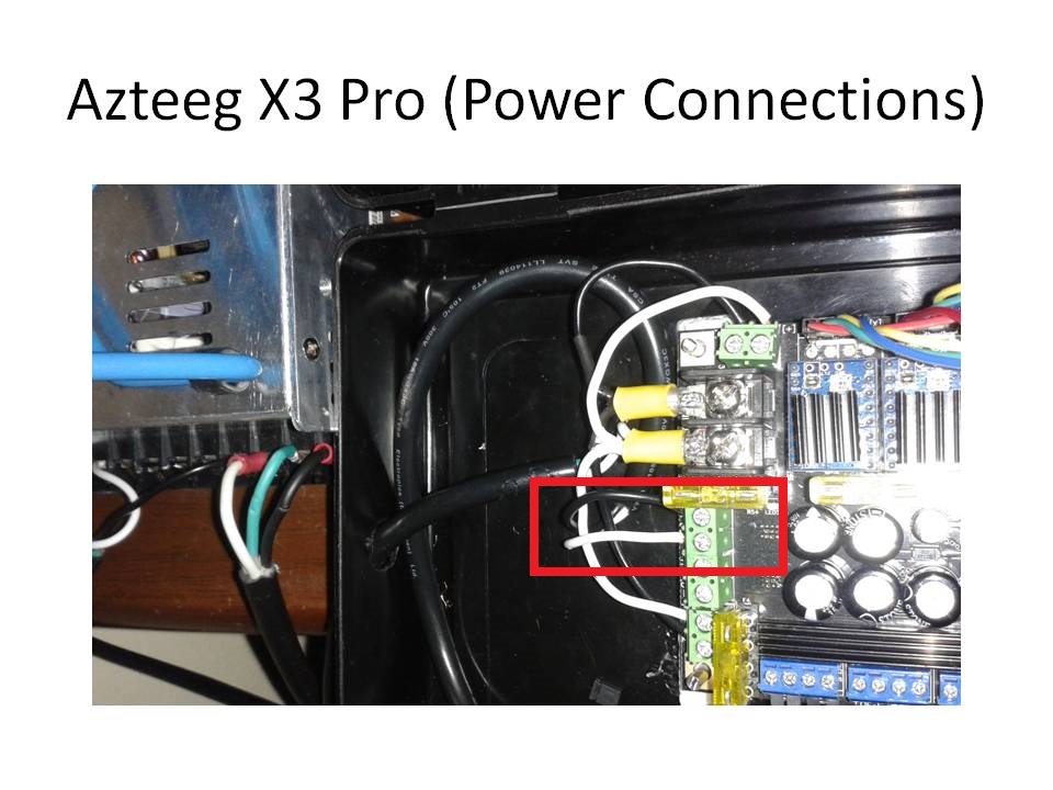
I assume the wires I have circled go to your bed heater. By the way it is a very dangerous practice that could leave you with blown component to use the same wire colors for input as you do outputs.

http://soliforum.com/i/?m5ibgBd.jpg

Printing since 2009 and still love it!
Anycubic 4MAX best $225 ever invested.
Voxelabs Proxima SLA. 6 inch 2k Mono LCD.
Anycubic Predator, massive Delta machine. 450 x 370 print envelope.

52 (edited by EMC2 Robo 2015-09-22 07:24:45)

Re: Extruder 1 and 2 do not spin - Repetier Firmware

Hello carl_m1968,

Thank you very much for that advice. Unfortunately I was limited in wire, so I used what I could find. But you definitely make me want to change the wire colors immediately.

Heated Bed:
I have tried many different types, but still not heating up. So far all I can tell

#define TEMP_SENSOR_BED -2

is the only one that reads correctly. But none of the bed sensors seem to work.

Any ideas about what I can try?

53 (edited by carl_m1968 2015-09-22 07:52:43)

Re: Extruder 1 and 2 do not spin - Repetier Firmware

Ok then let me ask this, what type of sensor is installed on the bed? We need to make sure all the hardware is accounted for and working and identified before diving to deep into firmware. Also what kind of heater is the bed using?

Printing since 2009 and still love it!
Anycubic 4MAX best $225 ever invested.
Voxelabs Proxima SLA. 6 inch 2k Mono LCD.
Anycubic Predator, massive Delta machine. 450 x 370 print envelope.

54

Re: Extruder 1 and 2 do not spin - Repetier Firmware

Hello carl_m1968,

In response to your questions

Ok then let me ask this, what type of sensor is installed on the bed? We need to make sure all the hardware is accounted for and working and identified before diving to deep into firmware. Also what kind of heater is the bed using?

Heated Bed should be running on Thermistor sensor and is a PCB Heated Bed.

I will attach some pictures to show you my heated bed. I purchased the bed from some seller online. I have not seen another bed similar to this.

This heated bed should be able to handle higher temperatures. What do you think?
http://soliforum.com/i/?wGxcWFA.jpghttp://soliforum.com/i/?8bJLuuT.jpg

55

Re: Extruder 1 and 2 do not spin - Repetier Firmware

You might want to go back in your buying history and try to track down the specs on that bed. That is very thick aluminum and what looks like a silicone heating pad sandwiched on top of foam. That being the case many of the silicone pads require 120 AC to work. At the very least if you are trying to heat the bed and extruders at the same time your little 25 amp supply is not going to work. Those silicone beds that are 12 volt powered pull 20 amps while they are heating up. For 3D printers the lowest rated supply you would want is 30 amps. I actually use 75 amps so i have overhead for add on's if needed. You can never have to much current and it is always safer to have too much than too little.

I would try to heat the bed only and take a measurement of your power supply output and see if it is still 12 volts and stable.

So are the Extruders working now and we are now stuck on the bed not heating?

Printing since 2009 and still love it!
Anycubic 4MAX best $225 ever invested.
Voxelabs Proxima SLA. 6 inch 2k Mono LCD.
Anycubic Predator, massive Delta machine. 450 x 370 print envelope.

56

Re: Extruder 1 and 2 do not spin - Repetier Firmware

Hello everyone,

I would like to first give a special and HUGE Thanks to "carl_m1968", you have been extremely helpful and extremely quick responding I am overwhelmed with JOY. You have shared a ton of great information with me and I thank you.

Latest update on "Extruder 1 and 2 do not spin":

- Swithed from Repetier to Marlin firmware
- Using configuration.h files given to me by "carl_m1968" (I have made a few changes according to my build)
- XYZ Motors working
- Extruder #1 working
- Heated Bed NOT working

In response to carl_m1968

At the very least if you are trying to heat the bed and extruders at the same time your little 25 amp supply is not going to work. Those silicone beds that are 12 volt powered pull 20 amps while they are heating up. For 3D printers the lowest rated supply you would want is 30 amps

When using Repetier firmware I was able to successfully Heat Bed and Extruder #1 without any issue. Why would it be different for Marlin?

What setting should I choose for Heated Bed to turn on?

Thank you:-)

57

Re: Extruder 1 and 2 do not spin - Repetier Firmware

EMC2 Robo wrote:

Hello everyone,

I would like to first give a special and HUGE Thanks to "carl_m1968", you have been extremely helpful and extremely quick responding I am overwhelmed with JOY. You have shared a ton of great information with me and I thank you.

Latest update on "Extruder 1 and 2 do not spin":

- Swithed from Repetier to Marlin firmware
- Using configuration.h files given to me by "carl_m1968" (I have made a few changes according to my build)
- XYZ Motors working
- Extruder #1 working
- Heated Bed NOT working

In response to carl_m1968

At the very least if you are trying to heat the bed and extruders at the same time your little 25 amp supply is not going to work. Those silicone beds that are 12 volt powered pull 20 amps while they are heating up. For 3D printers the lowest rated supply you would want is 30 amps

When using Repetier firmware I was able to successfully Heat Bed and Extruder #1 without any issue. Why would it be different for Marlin?

What setting should I choose for Heated Bed to turn on?

Thank you:-)


Lets see if we can get this bed working now.. I need to see your pins.h file for Marlin. Need to make sure the bed is assigned the right pin based on a 68 mainboard.

Also there may be an LED on the board that lights when the bed should be heating. See if that lights when you send a heat command. The schematic does not show one but most boards have one.

Printing since 2009 and still love it!
Anycubic 4MAX best $225 ever invested.
Voxelabs Proxima SLA. 6 inch 2k Mono LCD.
Anycubic Predator, massive Delta machine. 450 x 370 print envelope.

58

Re: Extruder 1 and 2 do not spin - Repetier Firmware

Ok, you are correct about the LED light, but it does not light up

Also there may be an LED on the board that lights when the bed should be heating. See if that lights when you send a heat command.

Here goes Pins.h file

#ifndef PINS_H
#define PINS_H


/****************************************************************************************
* Arduino Mega pin assignment
*
****************************************************************************************/
#if MOTHERBOARD == 3 || MOTHERBOARD == 33 || MOTHERBOARD == 34 || MOTHERBOARD == 35 || MOTHERBOARD == 77 || MOTHERBOARD == 67 || MOTHERBOARD == 68
#define KNOWN_BOARD 1

//////////////////FIX THIS//////////////
#ifndef __AVR_ATmega1280__
 #ifndef __AVR_ATmega2560__
 #error Oops!  Make sure you have 'Arduino Mega' selected from the 'Tools -> Boards' menu.
 #endif
#endif


// uncomment one of the following lines for RAMPS v1.3 or v1.0, comment both for v1.2 or 1.1
#define RAMPS_V_1_3
// #define RAMPS_V_1_0


#if MOTHERBOARD == 33 || MOTHERBOARD == 34 || MOTHERBOARD == 35 || MOTHERBOARD == 77 || MOTHERBOARD == 67 || MOTHERBOARD == 68

  #define LARGE_FLASH true

  #if MOTHERBOARD == 77
    #define X_STEP_PIN         54
    #define X_DIR_PIN          55
    #define X_ENABLE_PIN       38
    #define X_MIN_PIN           3
    #define X_MAX_PIN           -1   //2 //Max endstops default to disabled "-1", set to commented value to enable.

    #define Y_STEP_PIN         60
    #define Y_DIR_PIN          61
    #define Y_ENABLE_PIN       56
    #define Y_MIN_PIN          14
    #define Y_MAX_PIN          -1   //15

    #define Z_STEP_PIN         46
    #define Z_DIR_PIN          48
    #define Z_ENABLE_PIN       63
    #define Z_MIN_PIN          18
    #define Z_MAX_PIN          -1

    #define Y2_STEP_PIN        36
    #define Y2_DIR_PIN         34
    #define Y2_ENABLE_PIN      30

    #define Z2_STEP_PIN        36
    #define Z2_DIR_PIN         34
    #define Z2_ENABLE_PIN      30

    #define E0_STEP_PIN        26
    #define E0_DIR_PIN         28
    #define E0_ENABLE_PIN      24

    #define E1_STEP_PIN        36
    #define E1_DIR_PIN         34
    #define E1_ENABLE_PIN      30

    #define SDPOWER            -1
    #define SDSS               25//53
    #define LED_PIN            13

    #define BEEPER             33

  #else

    #define X_STEP_PIN         54
    #define X_DIR_PIN          55
    #define X_ENABLE_PIN       38
    #define X_MIN_PIN           3
    #define X_MAX_PIN           2

    #define Y_STEP_PIN         60
    #define Y_DIR_PIN          61
    #define Y_ENABLE_PIN       56
    #define Y_MIN_PIN          14
    #define Y_MAX_PIN          15

    #define Z_STEP_PIN         46
    #define Z_DIR_PIN          48
    #define Z_ENABLE_PIN       62
    #define Z_MIN_PIN          18
    #define Z_MAX_PIN          19

    #define Y2_STEP_PIN        36
    #define Y2_DIR_PIN         34
    #define Y2_ENABLE_PIN      30

    #define Z2_STEP_PIN        36
    #define Z2_DIR_PIN         34
    #define Z2_ENABLE_PIN      30

    #define E0_STEP_PIN        26
    #define E0_DIR_PIN         28
    #define E0_ENABLE_PIN      24

    #define E1_STEP_PIN        36
    #define E1_DIR_PIN         34
    #define E1_ENABLE_PIN      30

    #if MOTHERBOARD == 68
      #define E2_STEP_PIN        23
      #define E2_DIR_PIN         25
      #define E2_ENABLE_PIN      40

      #define E3_STEP_PIN        27
      #define E3_DIR_PIN         29
      #define E3_ENABLE_PIN      41

      #define E4_STEP_PIN        43
      #define E4_DIR_PIN         37
      #define E4_ENABLE_PIN      42
    #endif

    #define SDPOWER            1
    #define SDSS               53
    #define LED_PIN            13
  #endif

  #if MOTHERBOARD == 33 || MOTHERBOARD == 35 || MOTHERBOARD == 67 || MOTHERBOARD == 68
    #define FAN_PIN            4 // (Sprinter config)
  #else
    #define FAN_2_PIN            5 // IO pin. Buffer needed
  #endif

  #if MOTHERBOARD == 77
    #define FAN_PIN            8
  #endif

  #if MOTHERBOARD == 35
    #define CONTROLLERFAN_PIN  -1 //Pin used for the fan to cool controller
  #endif

  #define PS_ON_PIN          12

  #if defined(REPRAP_DISCOUNT_SMART_CONTROLLER) || defined(G3D_PANEL)
    #define KILL_PIN           41
  #else
    #define KILL_PIN           -1
  #endif

  #if MOTHERBOARD == 35
    #define HEATER_0_PIN       8
  #else
    #define HEATER_0_PIN       10   // EXTRUDER 1
  #endif

  #if MOTHERBOARD == 33 || MOTHERBOARD == 67
    #define HEATER_1_PIN       -1
  #else
    #define HEATER_1_PIN       9    // EXTRUDER 2 (FAN On Sprinter)
  #endif


  #if MOTHERBOARD == 77
    #define HEATER_0_PIN       10
    #define HEATER_1_PIN       12
    #define HEATER_2_PIN       6
  #elif MOTHERBOARD == 68
    #define HEATER_2_PIN       16
    #define HEATER_3_PIN       17
    #define HEATER_4_PIN       4
    #define HEATER_5_PIN       5
    #define HEATER_6_PIN       6
    #define HEATER_7_PIN       11
  #else
    #define HEATER_2_PIN       -1
  #endif

  #define TEMP_0_PIN         4   // ANALOG NUMBERING
  #define TEMP_1_PIN         15   // ANALOG NUMBERING
  #if MOTHERBOARD == 68
    #define TEMP_2_PIN         12   // ANALOG NUMBERING
    #define TEMP_3_PIN         11   // ANALOG NUMBERING
    #define TEMP_4_PIN         10   // ANALOG NUMBERING
    #define TC1                4    // ANALOG NUMBERING Thermo couple on Azteeg X3Pro
    #define TC2                5    // ANALOG NUMBERING Thermo couple on Azteeg X3Pro
  #else
    #define TEMP_2_PIN         -1   // ANALOG NUMBERING
  #endif

  #if MOTHERBOARD == 35
    #define HEATER_BED_PIN     -1    // NO BED
  #else
    #if MOTHERBOARD == 77
      #define HEATER_BED_PIN     9    // BED
    #else
      #define HEATER_BED_PIN     8    // BED
    #endif
  #endif

  #define TEMP_BED_PIN       14   // ANALOG NUMBERING

  #ifdef NUM_SERVOS
    #define SERVO0_PIN         11

    #if NUM_SERVOS > 1
      #define SERVO1_PIN         6
    #endif

    #if NUM_SERVOS > 2
      #define SERVO2_PIN         5
    #endif

    #if NUM_SERVOS > 3
      #define SERVO3_PIN         4
    #endif
  #endif

  #if MOTHERBOARD == 68
    #define BEEPER 33
  #endif

  #ifdef TEMP_STAT_LEDS
    #if MOTHERBOARD == 67
      #define STAT_LED_RED       6
      #define STAT_LED_BLUE     11
    #endif
  #endif

  #ifdef ULTRA_LCD

    #ifdef NEWPANEL
      #define LCD_PINS_RS 16
      #define LCD_PINS_ENABLE 17
      #define LCD_PINS_D4 23
      #define LCD_PINS_D5 25
      #define LCD_PINS_D6 27
      #define LCD_PINS_D7 29

      #ifdef REPRAP_DISCOUNT_SMART_CONTROLLER
        #define BEEPER 37

        #define BTN_EN1 31
        #define BTN_EN2 33
        #define BTN_ENC 35

        #define SDCARDDETECT 49
      #elif defined(LCD_I2C_PANELOLU2)
        #define BTN_EN1 47  //reverse if the encoder turns the wrong way.
        #define BTN_EN2 43
        #define BTN_ENC 32
        #define SDSS 53
        #define SDCARDDETECT -1
        #define KILL_PIN 41
      #elif defined(LCD_I2C_VIKI)
        #define BTN_EN1 22  //reverse if the encoder turns the wrong way.
        #define BTN_EN2 7
        #define BTN_ENC -1
        #define SDSS 53
        #define SDCARDDETECT 49
      #else
        //arduino pin which triggers an piezzo beeper
        #define BEEPER 33  // Beeper on AUX-4

        //buttons are directly attached using AUX-2
        #ifdef REPRAPWORLD_KEYPAD
          #define BTN_EN1 64 // encoder
          #define BTN_EN2 59 // encoder
          #define BTN_ENC 63 // enter button
          #define SHIFT_OUT 40 // shift register
          #define SHIFT_CLK 44 // shift register
          #define SHIFT_LD 42 // shift register
        #else
          #define BTN_EN1 37
          #define BTN_EN2 35
          #define BTN_ENC 31  //the click
        #endif

        #ifdef G3D_PANEL
          #define SDCARDDETECT 49
        #else
          #define SDCARDDETECT -1  // Ramps does not use this port
        #endif

      #endif

      #if MOTHERBOARD == 77
        #define BEEPER -1

        #define LCD_PINS_RS 27
        #define LCD_PINS_ENABLE 29
        #define LCD_PINS_D4 37
        #define LCD_PINS_D5 35
        #define LCD_PINS_D6 33
        #define LCD_PINS_D7 31

       //buttons
       #define BTN_EN1 16
       #define BTN_EN2 17
       #define BTN_ENC 23 //the click

    #endif
    #else //old style panel with shift register
      //arduino pin witch triggers an piezzo beeper
      #define BEEPER 33        //No Beeper added

      //buttons are attached to a shift register
    // Not wired this yet
      //#define SHIFT_CLK 38
      //#define SHIFT_LD 42
      //#define SHIFT_OUT 40
      //#define SHIFT_EN 17

      #define LCD_PINS_RS 16
      #define LCD_PINS_ENABLE 17
      #define LCD_PINS_D4 23
      #define LCD_PINS_D5 25
      #define LCD_PINS_D6 27
      #define LCD_PINS_D7 29
    #endif
  #endif //ULTRA_LCD

#else // RAMPS_V_1_1 or RAMPS_V_1_2 as default (MOTHERBOARD == 3)

#define X_STEP_PIN         26
#define X_DIR_PIN          28
#define X_ENABLE_PIN       24
#define X_MIN_PIN           3
#define X_MAX_PIN          -1    //2

#define Y_STEP_PIN         38
#define Y_DIR_PIN          40
#define Y_ENABLE_PIN       36
#define Y_MIN_PIN          16
#define Y_MAX_PIN          -1    //17

#define Z_STEP_PIN         44
#define Z_DIR_PIN          46
#define Z_ENABLE_PIN       42
#define Z_MIN_PIN          18
#define Z_MAX_PIN          -1    //19

#define E0_STEP_PIN         32
#define E0_DIR_PIN          34
#define E0_ENABLE_PIN       30

#define SDPOWER            48
#define SDSS               53
#define LED_PIN            13
#define PS_ON_PIN          -1
#define KILL_PIN           -1

#ifdef RAMPS_V_1_0 // RAMPS_V_1_0
  #define HEATER_0_PIN     12    // RAMPS 1.0
  #define HEATER_BED_PIN   -1    // RAMPS 1.0
  #define FAN_PIN          11    // RAMPS 1.0
#else // RAMPS_V_1_1 or RAMPS_V_1_2
  #define HEATER_0_PIN     10    // RAMPS 1.1
  #define HEATER_BED_PIN    8    // RAMPS 1.1
  #define FAN_PIN           9    // RAMPS 1.1
#endif
#define HEATER_1_PIN        -1
#define HEATER_2_PIN        -1
#define TEMP_0_PIN          2    // MUST USE ANALOG INPUT NUMBERING NOT DIGITAL OUTPUT NUMBERING!!!!!!!!!
#define TEMP_1_PIN          -1
#define TEMP_2_PIN          -1
#define TEMP_BED_PIN        1    // MUST USE ANALOG INPUT NUMBERING NOT DIGITAL OUTPUT NUMBERING!!!!!!!!!

#endif // MOTHERBOARD == 33 || MOTHERBOARD == 34 || MOTHERBOARD == 35 || MOTHERBOARD == 77

// SPI for Max6675 Thermocouple

#ifndef SDSUPPORT
// these pins are defined in the SD library if building with SD support
  #define SCK_PIN          52
  #define MISO_PIN         50
  #define MOSI_PIN         51
  #define MAX6675_SS       53
#else
  #define MAX6675_SS       49
#endif

#endif //MOTHERBOARD == 3 || MOTHERBOARD == 33 || MOTHERBOARD == 34 || MOTHERBOARD == 35 || MOTHERBOARD == 77

/****************************************************************************************
* Duemilanove w/ ATMega328P pin assignment
*
****************************************************************************************/
#if MOTHERBOARD == 4
#define KNOWN_BOARD 1

#ifndef __AVR_ATmega328P__
#error Oops!  Make sure you have 'Arduino Duemilanove w/ ATMega328' selected from the 'Tools -> Boards' menu.
#endif

#define X_STEP_PIN         19
#define X_DIR_PIN          18
#define X_ENABLE_PIN       -1
#define X_STOP_PIN         17

#define Y_STEP_PIN         10
#define Y_DIR_PIN           7
#define Y_ENABLE_PIN       -1
#define Y_STOP_PIN          8

#define Z_STEP_PIN         13
#define Z_DIR_PIN           3
#define Z_ENABLE_PIN        2
#define Z_STOP_PIN          4

#define E0_STEP_PIN         11
#define E0_DIR_PIN          12
#define E0_ENABLE_PIN       -1

#define SDPOWER          -1
#define SDSS          -1
#define LED_PIN            -1
#define FAN_PIN             5
#define PS_ON_PIN          -1
#define KILL_PIN           -1

#define HEATER_0_PIN        6
#define HEATER_1_PIN        -1
#define HEATER_2_PIN        -1
#define TEMP_0_PIN          0    // MUST USE ANALOG INPUT NUMBERING NOT DIGITAL OUTPUT NUMBERING!!!!!!!!!
#define TEMP_1_PIN          -1
#define TEMP_2_PIN          -1
#define HEATER_BED_PIN      -1
#define TEMP_BED_PIN        -1

#endif

/****************************************************************************************
* Minitronics v1.0
*
****************************************************************************************/
#if MOTHERBOARD == 702
 #define KNOWN_BOARD 1


 #ifndef __AVR_ATmega1281__
 #error Oops! Make sure you have 'Minitronics ' selected from the 'Tools -> Boards' menu.
 #endif

 #define LARGE_FLASH        true

 #define X_STEP_PIN 48
 #define X_DIR_PIN 47
 #define X_ENABLE_PIN 49
 #define X_MIN_PIN 5
 #define X_MAX_PIN -1 //2 //Max endstops default to disabled "-1", set to commented value to enable.

 #define Y_STEP_PIN 39 // A6
 #define Y_DIR_PIN 40 // A0
 #define Y_ENABLE_PIN 38
 #define Y_MIN_PIN 2
 #define Y_MAX_PIN -1 //15

 #define Z_STEP_PIN 42 // A2
 #define Z_DIR_PIN 43 // A6
 #define Z_ENABLE_PIN 41 // A1
 #define Z_MIN_PIN 6
 #define Z_MAX_PIN -1

 #define E0_STEP_PIN 45
 #define E0_DIR_PIN 44
 #define E0_ENABLE_PIN 27

 #define E1_STEP_PIN 36
 #define E1_DIR_PIN 35
 #define E1_ENABLE_PIN 37

 #define E2_STEP_PIN -1
 #define E2_DIR_PIN -1
 #define E2_ENABLE_PIN -1

 #define SDPOWER -1
 #define SDSS 16
 #define LED_PIN 46

 #define FAN_PIN 9
 #define FAN2_PIN -1
 #define PS_ON_PIN -1
 #define KILL_PIN -1

 #define HEATER_0_PIN 7 // EXTRUDER 1
 #define HEATER_1_PIN 8 // EXTRUDER 2
 #define HEATER_2_PIN -1


 #define TEMP_0_PIN 7 // ANALOG NUMBERING
 #define TEMP_1_PIN 6 // ANALOG NUMBERING
 #define TEMP_2_PIN -1 // ANALOG NUMBERING

 #define HEATER_BED_PIN 3 // BED
 #define TEMP_BED_PIN 6 // ANALOG NUMBERING

 #define BEEPER -1


 #define LCD_PINS_RS -1
 #define LCD_PINS_ENABLE -1
 #define LCD_PINS_D4 -1
 #define LCD_PINS_D5 -1
 #define LCD_PINS_D6 -1
 #define LCD_PINS_D7 -1


 //buttons are directly attached using keypad
 #define BTN_EN1 -1
 #define BTN_EN2 -1
 #define BTN_ENC -1 //the click

 #define BLEN_C 2
 #define BLEN_B 1
 #define BLEN_A 0

 #define SDCARDDETECT -1    // Megatronics does not use this port

   //encoder rotation values
 #define encrot0 0
 #define encrot1 2
 #define encrot2 3
 #define encrot3 1

#endif

/****************************************************************************************
* Cheaptronic v1.0
*
****************************************************************************************/
#if MOTHERBOARD == 2
 #define KNOWN_BOARD 1

 #ifndef __AVR_ATmega2560__
 #error Oops! Make sure you have 'Arduino Mega' selected from the 'Tools -> Boards' menu.
 #endif

 #define LARGE_FLASH        true

 //X motor stepper
 #define X_STEP_PIN 14
 #define X_DIR_PIN 15
 #define X_ENABLE_PIN 24

 //X endstop
 #define X_MIN_PIN 3
 #define X_MAX_PIN -1

 //Y motor stepper
 #define Y_STEP_PIN 35
 #define Y_DIR_PIN 36
 #define Y_ENABLE_PIN 31

 //Y endstop
 #define Y_MIN_PIN 2
 #define Y_MAX_PIN -1

 //Z motor stepper
 #define Z_STEP_PIN 40
 #define Z_DIR_PIN 41
 #define Z_ENABLE_PIN 37

 //Z endstop
 #define Z_MIN_PIN 5
 #define Z_MAX_PIN -1

 //Extruder 0 stepper
 #define E0_STEP_PIN 26
 #define E0_DIR_PIN 28
 #define E0_ENABLE_PIN 25

 //Extruder 1 stepper
 #define E1_STEP_PIN 33
 #define E1_DIR_PIN 34
 #define E1_ENABLE_PIN 30

 #define SDPOWER -1
 #define SDSS -1
 #define LED_PIN -1

 //FAN
 #define FAN_PIN -1

 #define PS_ON_PIN -1
 #define KILL_PIN -1

 #define HEATER_0_PIN 19 // EXTRUDER 1
 #define HEATER_1_PIN 23 // EXTRUDER 2
 //HeatedBad
 #define HEATER_BED_PIN 22
 //Cheaptronic v1.0 hasent EXTRUDER 3
 #define HEATER_2_PIN -1

 //Temperature sensors
 #define TEMP_0_PIN 15
 #define TEMP_1_PIN 14
 #define TEMP_2_PIN -1
 #define TEMP_BED_PIN 13

 //Cheaptronic v1.0 dont support LCD
 #define LCD_PINS_RS -1
 #define LCD_PINS_ENABLE -1
 #define LCD_PINS_D4 -1
 #define LCD_PINS_D5 -1
 #define LCD_PINS_D6 -1
 #define LCD_PINS_D7 -1

 //Cheaptronic v1.0 dont support keypad
 #define BTN_EN1 -1
 #define BTN_EN2 -1
 #define BTN_ENC -1

 #define BLEN_C 2
 #define BLEN_B 1
 #define BLEN_A 0

 //Cheaptronic v1.0 does not use this port
 #define SDCARDDETECT -1

 //encoder rotation values
 #define encrot0 0
 #define encrot1 2
 #define encrot2 3
 #define encrot3 1

#endif


#ifndef KNOWN_BOARD
#error Unknown MOTHERBOARD value in configuration.h
#endif

//List of pins which to ignore when asked to change by gcode, 0 and 1 are RX and TX, do not mess with those!
#define _E0_PINS E0_STEP_PIN, E0_DIR_PIN, E0_ENABLE_PIN, HEATER_0_PIN,
#if EXTRUDERS > 1
  #define _E1_PINS E1_STEP_PIN, E1_DIR_PIN, E1_ENABLE_PIN, HEATER_1_PIN,
#else
  #define _E1_PINS
#endif
#if EXTRUDERS > 2
  #define _E2_PINS E2_STEP_PIN, E2_DIR_PIN, E2_ENABLE_PIN, HEATER_2_PIN,
#else
  #define _E2_PINS
#endif

#ifdef X_STOP_PIN
  #if X_HOME_DIR < 0
    #define X_MIN_PIN X_STOP_PIN
    #define X_MAX_PIN -1
  #else
    #define X_MIN_PIN -1
    #define X_MAX_PIN X_STOP_PIN
  #endif
#endif

#ifdef Y_STOP_PIN
  #if Y_HOME_DIR < 0
    #define Y_MIN_PIN Y_STOP_PIN
    #define Y_MAX_PIN -1
  #else
    #define Y_MIN_PIN -1
    #define Y_MAX_PIN Y_STOP_PIN
  #endif
#endif

#ifdef Z_STOP_PIN
  #if Z_HOME_DIR < 0
    #define Z_MIN_PIN Z_STOP_PIN
    #define Z_MAX_PIN -1
  #else
    #define Z_MIN_PIN -1
    #define Z_MAX_PIN Z_STOP_PIN
  #endif
#endif

#ifdef DISABLE_MAX_ENDSTOPS
#define X_MAX_PIN          -1
#define Y_MAX_PIN          -1
#define Z_MAX_PIN          -1
#endif

#ifdef DISABLE_MIN_ENDSTOPS
#define X_MIN_PIN          -1
#define Y_MIN_PIN          -1
#define Z_MIN_PIN          -1
#endif

#define SENSITIVE_PINS {0, 1, X_STEP_PIN, X_DIR_PIN, X_ENABLE_PIN, X_MIN_PIN, X_MAX_PIN, Y_STEP_PIN, Y_DIR_PIN, Y_ENABLE_PIN, Y_MIN_PIN, Y_MAX_PIN, Z_STEP_PIN, Z_DIR_PIN, Z_ENABLE_PIN, Z_MIN_PIN, Z_MAX_PIN, PS_ON_PIN, \
                        HEATER_BED_PIN, FAN_PIN,                  \
                        _E0_PINS _E1_PINS _E2_PINS             \
                        analogInputToDigitalPin(TEMP_0_PIN), analogInputToDigitalPin(TEMP_1_PIN), analogInputToDigitalPin(TEMP_2_PIN), analogInputToDigitalPin(TEMP_BED_PIN) }
#endif

59 (edited by carl_m1968 2015-09-22 23:24:09)

Re: Extruder 1 and 2 do not spin - Repetier Firmware

EMC2 Robo wrote:

Ok, you are correct about the LED light, but it does not light up

Also there may be an LED on the board that lights when the bed should be heating. See if that lights when you send a heat command.

Here goes Pins.h file

#ifndef PINS_H
#define PINS_H


/****************************************************************************************
* Arduino Mega pin assignment
*
****************************************************************************************/
#if MOTHERBOARD == 3 || MOTHERBOARD == 33 || MOTHERBOARD == 34 || MOTHERBOARD == 35 || MOTHERBOARD == 77 || MOTHERBOARD == 67 || MOTHERBOARD == 68
#define KNOWN_BOARD 1

//////////////////FIX THIS//////////////
#ifndef __AVR_ATmega1280__
 #ifndef __AVR_ATmega2560__
 #error Oops!  Make sure you have 'Arduino Mega' selected from the 'Tools -> Boards' menu.
 #endif
#endif


// uncomment one of the following lines for RAMPS v1.3 or v1.0, comment both for v1.2 or 1.1
#define RAMPS_V_1_3
// #define RAMPS_V_1_0


#if MOTHERBOARD == 33 || MOTHERBOARD == 34 || MOTHERBOARD == 35 || MOTHERBOARD == 77 || MOTHERBOARD == 67 || MOTHERBOARD == 68

  #define LARGE_FLASH true

  #if MOTHERBOARD == 77
    #define X_STEP_PIN         54
    #define X_DIR_PIN          55
    #define X_ENABLE_PIN       38
    #define X_MIN_PIN           3
    #define X_MAX_PIN           -1   //2 //Max endstops default to disabled "-1", set to commented value to enable.

    #define Y_STEP_PIN         60
    #define Y_DIR_PIN          61
    #define Y_ENABLE_PIN       56
    #define Y_MIN_PIN          14
    #define Y_MAX_PIN          -1   //15

    #define Z_STEP_PIN         46
    #define Z_DIR_PIN          48
    #define Z_ENABLE_PIN       63
    #define Z_MIN_PIN          18
    #define Z_MAX_PIN          -1

    #define Y2_STEP_PIN        36
    #define Y2_DIR_PIN         34
    #define Y2_ENABLE_PIN      30

    #define Z2_STEP_PIN        36
    #define Z2_DIR_PIN         34
    #define Z2_ENABLE_PIN      30

    #define E0_STEP_PIN        26
    #define E0_DIR_PIN         28
    #define E0_ENABLE_PIN      24

    #define E1_STEP_PIN        36
    #define E1_DIR_PIN         34
    #define E1_ENABLE_PIN      30

    #define SDPOWER            -1
    #define SDSS               25//53
    #define LED_PIN            13

    #define BEEPER             33

  #else

    #define X_STEP_PIN         54
    #define X_DIR_PIN          55
    #define X_ENABLE_PIN       38
    #define X_MIN_PIN           3
    #define X_MAX_PIN           2

    #define Y_STEP_PIN         60
    #define Y_DIR_PIN          61
    #define Y_ENABLE_PIN       56
    #define Y_MIN_PIN          14
    #define Y_MAX_PIN          15

    #define Z_STEP_PIN         46
    #define Z_DIR_PIN          48
    #define Z_ENABLE_PIN       62
    #define Z_MIN_PIN          18
    #define Z_MAX_PIN          19

    #define Y2_STEP_PIN        36
    #define Y2_DIR_PIN         34
    #define Y2_ENABLE_PIN      30

    #define Z2_STEP_PIN        36
    #define Z2_DIR_PIN         34
    #define Z2_ENABLE_PIN      30

    #define E0_STEP_PIN        26
    #define E0_DIR_PIN         28
    #define E0_ENABLE_PIN      24

    #define E1_STEP_PIN        36
    #define E1_DIR_PIN         34
    #define E1_ENABLE_PIN      30

    #if MOTHERBOARD == 68
      #define E2_STEP_PIN        23
      #define E2_DIR_PIN         25
      #define E2_ENABLE_PIN      40

      #define E3_STEP_PIN        27
      #define E3_DIR_PIN         29
      #define E3_ENABLE_PIN      41

      #define E4_STEP_PIN        43
      #define E4_DIR_PIN         37
      #define E4_ENABLE_PIN      42
    #endif

    #define SDPOWER            1
    #define SDSS               53
    #define LED_PIN            13
  #endif

  #if MOTHERBOARD == 33 || MOTHERBOARD == 35 || MOTHERBOARD == 67 || MOTHERBOARD == 68
    #define FAN_PIN            4 // (Sprinter config)
  #else
    #define FAN_2_PIN            5 // IO pin. Buffer needed
  #endif

  #if MOTHERBOARD == 77
    #define FAN_PIN            8
  #endif

  #if MOTHERBOARD == 35
    #define CONTROLLERFAN_PIN  -1 //Pin used for the fan to cool controller
  #endif

  #define PS_ON_PIN          12

  #if defined(REPRAP_DISCOUNT_SMART_CONTROLLER) || defined(G3D_PANEL)
    #define KILL_PIN           41
  #else
    #define KILL_PIN           -1
  #endif

  #if MOTHERBOARD == 35
    #define HEATER_0_PIN       8
  #else
    #define HEATER_0_PIN       10   // EXTRUDER 1
  #endif

  #if MOTHERBOARD == 33 || MOTHERBOARD == 67
    #define HEATER_1_PIN       -1
  #else
    #define HEATER_1_PIN       9    // EXTRUDER 2 (FAN On Sprinter)
  #endif


  #if MOTHERBOARD == 77
    #define HEATER_0_PIN       10
    #define HEATER_1_PIN       12
    #define HEATER_2_PIN       6
  #elif MOTHERBOARD == 68
    #define HEATER_2_PIN       16
    #define HEATER_3_PIN       17
    #define HEATER_4_PIN       4
    #define HEATER_5_PIN       5
    #define HEATER_6_PIN       6
    #define HEATER_7_PIN       11
  #else
    #define HEATER_2_PIN       -1
  #endif

  #define TEMP_0_PIN         4   // ANALOG NUMBERING
  #define TEMP_1_PIN         15   // ANALOG NUMBERING
  #if MOTHERBOARD == 68
    #define TEMP_2_PIN         12   // ANALOG NUMBERING
    #define TEMP_3_PIN         11   // ANALOG NUMBERING
    #define TEMP_4_PIN         10   // ANALOG NUMBERING
    #define TC1                4    // ANALOG NUMBERING Thermo couple on Azteeg X3Pro
    #define TC2                5    // ANALOG NUMBERING Thermo couple on Azteeg X3Pro
  #else
    #define TEMP_2_PIN         -1   // ANALOG NUMBERING
  #endif

  #if MOTHERBOARD == 35
    #define HEATER_BED_PIN     -1    // NO BED
  #else
    #if MOTHERBOARD == 77
      #define HEATER_BED_PIN     9    // BED
    #else
      #define HEATER_BED_PIN     8    // BED
    #endif
  #endif

  #define TEMP_BED_PIN       14   // ANALOG NUMBERING

  #ifdef NUM_SERVOS
    #define SERVO0_PIN         11

    #if NUM_SERVOS > 1
      #define SERVO1_PIN         6
    #endif

    #if NUM_SERVOS > 2
      #define SERVO2_PIN         5
    #endif

    #if NUM_SERVOS > 3
      #define SERVO3_PIN         4
    #endif
  #endif

  #if MOTHERBOARD == 68
    #define BEEPER 33
  #endif

  #ifdef TEMP_STAT_LEDS
    #if MOTHERBOARD == 67
      #define STAT_LED_RED       6
      #define STAT_LED_BLUE     11
    #endif
  #endif

  #ifdef ULTRA_LCD

    #ifdef NEWPANEL
      #define LCD_PINS_RS 16
      #define LCD_PINS_ENABLE 17
      #define LCD_PINS_D4 23
      #define LCD_PINS_D5 25
      #define LCD_PINS_D6 27
      #define LCD_PINS_D7 29

      #ifdef REPRAP_DISCOUNT_SMART_CONTROLLER
        #define BEEPER 37

        #define BTN_EN1 31
        #define BTN_EN2 33
        #define BTN_ENC 35

        #define SDCARDDETECT 49
      #elif defined(LCD_I2C_PANELOLU2)
        #define BTN_EN1 47  //reverse if the encoder turns the wrong way.
        #define BTN_EN2 43
        #define BTN_ENC 32
        #define SDSS 53
        #define SDCARDDETECT -1
        #define KILL_PIN 41
      #elif defined(LCD_I2C_VIKI)
        #define BTN_EN1 22  //reverse if the encoder turns the wrong way.
        #define BTN_EN2 7
        #define BTN_ENC -1
        #define SDSS 53
        #define SDCARDDETECT 49
      #else
        //arduino pin which triggers an piezzo beeper
        #define BEEPER 33  // Beeper on AUX-4

        //buttons are directly attached using AUX-2
        #ifdef REPRAPWORLD_KEYPAD
          #define BTN_EN1 64 // encoder
          #define BTN_EN2 59 // encoder
          #define BTN_ENC 63 // enter button
          #define SHIFT_OUT 40 // shift register
          #define SHIFT_CLK 44 // shift register
          #define SHIFT_LD 42 // shift register
        #else
          #define BTN_EN1 37
          #define BTN_EN2 35
          #define BTN_ENC 31  //the click
        #endif

        #ifdef G3D_PANEL
          #define SDCARDDETECT 49
        #else
          #define SDCARDDETECT -1  // Ramps does not use this port
        #endif

      #endif

      #if MOTHERBOARD == 77
        #define BEEPER -1

        #define LCD_PINS_RS 27
        #define LCD_PINS_ENABLE 29
        #define LCD_PINS_D4 37
        #define LCD_PINS_D5 35
        #define LCD_PINS_D6 33
        #define LCD_PINS_D7 31

       //buttons
       #define BTN_EN1 16
       #define BTN_EN2 17
       #define BTN_ENC 23 //the click

    #endif
    #else //old style panel with shift register
      //arduino pin witch triggers an piezzo beeper
      #define BEEPER 33        //No Beeper added

      //buttons are attached to a shift register
    // Not wired this yet
      //#define SHIFT_CLK 38
      //#define SHIFT_LD 42
      //#define SHIFT_OUT 40
      //#define SHIFT_EN 17

      #define LCD_PINS_RS 16
      #define LCD_PINS_ENABLE 17
      #define LCD_PINS_D4 23
      #define LCD_PINS_D5 25
      #define LCD_PINS_D6 27
      #define LCD_PINS_D7 29
    #endif
  #endif //ULTRA_LCD

#else // RAMPS_V_1_1 or RAMPS_V_1_2 as default (MOTHERBOARD == 3)

#define X_STEP_PIN         26
#define X_DIR_PIN          28
#define X_ENABLE_PIN       24
#define X_MIN_PIN           3
#define X_MAX_PIN          -1    //2

#define Y_STEP_PIN         38
#define Y_DIR_PIN          40
#define Y_ENABLE_PIN       36
#define Y_MIN_PIN          16
#define Y_MAX_PIN          -1    //17

#define Z_STEP_PIN         44
#define Z_DIR_PIN          46
#define Z_ENABLE_PIN       42
#define Z_MIN_PIN          18
#define Z_MAX_PIN          -1    //19

#define E0_STEP_PIN         32
#define E0_DIR_PIN          34
#define E0_ENABLE_PIN       30

#define SDPOWER            48
#define SDSS               53
#define LED_PIN            13
#define PS_ON_PIN          -1
#define KILL_PIN           -1

#ifdef RAMPS_V_1_0 // RAMPS_V_1_0
  #define HEATER_0_PIN     12    // RAMPS 1.0
  #define HEATER_BED_PIN   -1    // RAMPS 1.0
  #define FAN_PIN          11    // RAMPS 1.0
#else // RAMPS_V_1_1 or RAMPS_V_1_2
  #define HEATER_0_PIN     10    // RAMPS 1.1
  #define HEATER_BED_PIN    8    // RAMPS 1.1
  #define FAN_PIN           9    // RAMPS 1.1
#endif
#define HEATER_1_PIN        -1
#define HEATER_2_PIN        -1
#define TEMP_0_PIN          2    // MUST USE ANALOG INPUT NUMBERING NOT DIGITAL OUTPUT NUMBERING!!!!!!!!!
#define TEMP_1_PIN          -1
#define TEMP_2_PIN          -1
#define TEMP_BED_PIN        1    // MUST USE ANALOG INPUT NUMBERING NOT DIGITAL OUTPUT NUMBERING!!!!!!!!!

#endif // MOTHERBOARD == 33 || MOTHERBOARD == 34 || MOTHERBOARD == 35 || MOTHERBOARD == 77

// SPI for Max6675 Thermocouple

#ifndef SDSUPPORT
// these pins are defined in the SD library if building with SD support
  #define SCK_PIN          52
  #define MISO_PIN         50
  #define MOSI_PIN         51
  #define MAX6675_SS       53
#else
  #define MAX6675_SS       49
#endif

#endif //MOTHERBOARD == 3 || MOTHERBOARD == 33 || MOTHERBOARD == 34 || MOTHERBOARD == 35 || MOTHERBOARD == 77

/****************************************************************************************
* Duemilanove w/ ATMega328P pin assignment
*
****************************************************************************************/
#if MOTHERBOARD == 4
#define KNOWN_BOARD 1

#ifndef __AVR_ATmega328P__
#error Oops!  Make sure you have 'Arduino Duemilanove w/ ATMega328' selected from the 'Tools -> Boards' menu.
#endif

#define X_STEP_PIN         19
#define X_DIR_PIN          18
#define X_ENABLE_PIN       -1
#define X_STOP_PIN         17

#define Y_STEP_PIN         10
#define Y_DIR_PIN           7
#define Y_ENABLE_PIN       -1
#define Y_STOP_PIN          8

#define Z_STEP_PIN         13
#define Z_DIR_PIN           3
#define Z_ENABLE_PIN        2
#define Z_STOP_PIN          4

#define E0_STEP_PIN         11
#define E0_DIR_PIN          12
#define E0_ENABLE_PIN       -1

#define SDPOWER          -1
#define SDSS          -1
#define LED_PIN            -1
#define FAN_PIN             5
#define PS_ON_PIN          -1
#define KILL_PIN           -1

#define HEATER_0_PIN        6
#define HEATER_1_PIN        -1
#define HEATER_2_PIN        -1
#define TEMP_0_PIN          0    // MUST USE ANALOG INPUT NUMBERING NOT DIGITAL OUTPUT NUMBERING!!!!!!!!!
#define TEMP_1_PIN          -1
#define TEMP_2_PIN          -1
#define HEATER_BED_PIN      -1
#define TEMP_BED_PIN        -1

#endif

/****************************************************************************************
* Minitronics v1.0
*
****************************************************************************************/
#if MOTHERBOARD == 702
 #define KNOWN_BOARD 1


 #ifndef __AVR_ATmega1281__
 #error Oops! Make sure you have 'Minitronics ' selected from the 'Tools -> Boards' menu.
 #endif

 #define LARGE_FLASH        true

 #define X_STEP_PIN 48
 #define X_DIR_PIN 47
 #define X_ENABLE_PIN 49
 #define X_MIN_PIN 5
 #define X_MAX_PIN -1 //2 //Max endstops default to disabled "-1", set to commented value to enable.

 #define Y_STEP_PIN 39 // A6
 #define Y_DIR_PIN 40 // A0
 #define Y_ENABLE_PIN 38
 #define Y_MIN_PIN 2
 #define Y_MAX_PIN -1 //15

 #define Z_STEP_PIN 42 // A2
 #define Z_DIR_PIN 43 // A6
 #define Z_ENABLE_PIN 41 // A1
 #define Z_MIN_PIN 6
 #define Z_MAX_PIN -1

 #define E0_STEP_PIN 45
 #define E0_DIR_PIN 44
 #define E0_ENABLE_PIN 27

 #define E1_STEP_PIN 36
 #define E1_DIR_PIN 35
 #define E1_ENABLE_PIN 37

 #define E2_STEP_PIN -1
 #define E2_DIR_PIN -1
 #define E2_ENABLE_PIN -1

 #define SDPOWER -1
 #define SDSS 16
 #define LED_PIN 46

 #define FAN_PIN 9
 #define FAN2_PIN -1
 #define PS_ON_PIN -1
 #define KILL_PIN -1

 #define HEATER_0_PIN 7 // EXTRUDER 1
 #define HEATER_1_PIN 8 // EXTRUDER 2
 #define HEATER_2_PIN -1


 #define TEMP_0_PIN 7 // ANALOG NUMBERING
 #define TEMP_1_PIN 6 // ANALOG NUMBERING
 #define TEMP_2_PIN -1 // ANALOG NUMBERING

 #define HEATER_BED_PIN 3 // BED
 #define TEMP_BED_PIN 6 // ANALOG NUMBERING

 #define BEEPER -1


 #define LCD_PINS_RS -1
 #define LCD_PINS_ENABLE -1
 #define LCD_PINS_D4 -1
 #define LCD_PINS_D5 -1
 #define LCD_PINS_D6 -1
 #define LCD_PINS_D7 -1


 //buttons are directly attached using keypad
 #define BTN_EN1 -1
 #define BTN_EN2 -1
 #define BTN_ENC -1 //the click

 #define BLEN_C 2
 #define BLEN_B 1
 #define BLEN_A 0

 #define SDCARDDETECT -1    // Megatronics does not use this port

   //encoder rotation values
 #define encrot0 0
 #define encrot1 2
 #define encrot2 3
 #define encrot3 1

#endif

/****************************************************************************************
* Cheaptronic v1.0
*
****************************************************************************************/
#if MOTHERBOARD == 2
 #define KNOWN_BOARD 1

 #ifndef __AVR_ATmega2560__
 #error Oops! Make sure you have 'Arduino Mega' selected from the 'Tools -> Boards' menu.
 #endif

 #define LARGE_FLASH        true

 //X motor stepper
 #define X_STEP_PIN 14
 #define X_DIR_PIN 15
 #define X_ENABLE_PIN 24

 //X endstop
 #define X_MIN_PIN 3
 #define X_MAX_PIN -1

 //Y motor stepper
 #define Y_STEP_PIN 35
 #define Y_DIR_PIN 36
 #define Y_ENABLE_PIN 31

 //Y endstop
 #define Y_MIN_PIN 2
 #define Y_MAX_PIN -1

 //Z motor stepper
 #define Z_STEP_PIN 40
 #define Z_DIR_PIN 41
 #define Z_ENABLE_PIN 37

 //Z endstop
 #define Z_MIN_PIN 5
 #define Z_MAX_PIN -1

 //Extruder 0 stepper
 #define E0_STEP_PIN 26
 #define E0_DIR_PIN 28
 #define E0_ENABLE_PIN 25

 //Extruder 1 stepper
 #define E1_STEP_PIN 33
 #define E1_DIR_PIN 34
 #define E1_ENABLE_PIN 30

 #define SDPOWER -1
 #define SDSS -1
 #define LED_PIN -1

 //FAN
 #define FAN_PIN -1

 #define PS_ON_PIN -1
 #define KILL_PIN -1

 #define HEATER_0_PIN 19 // EXTRUDER 1
 #define HEATER_1_PIN 23 // EXTRUDER 2
 //HeatedBad
 #define HEATER_BED_PIN 22
 //Cheaptronic v1.0 hasent EXTRUDER 3
 #define HEATER_2_PIN -1

 //Temperature sensors
 #define TEMP_0_PIN 15
 #define TEMP_1_PIN 14
 #define TEMP_2_PIN -1
 #define TEMP_BED_PIN 13

 //Cheaptronic v1.0 dont support LCD
 #define LCD_PINS_RS -1
 #define LCD_PINS_ENABLE -1
 #define LCD_PINS_D4 -1
 #define LCD_PINS_D5 -1
 #define LCD_PINS_D6 -1
 #define LCD_PINS_D7 -1

 //Cheaptronic v1.0 dont support keypad
 #define BTN_EN1 -1
 #define BTN_EN2 -1
 #define BTN_ENC -1

 #define BLEN_C 2
 #define BLEN_B 1
 #define BLEN_A 0

 //Cheaptronic v1.0 does not use this port
 #define SDCARDDETECT -1

 //encoder rotation values
 #define encrot0 0
 #define encrot1 2
 #define encrot2 3
 #define encrot3 1

#endif


#ifndef KNOWN_BOARD
#error Unknown MOTHERBOARD value in configuration.h
#endif

//List of pins which to ignore when asked to change by gcode, 0 and 1 are RX and TX, do not mess with those!
#define _E0_PINS E0_STEP_PIN, E0_DIR_PIN, E0_ENABLE_PIN, HEATER_0_PIN,
#if EXTRUDERS > 1
  #define _E1_PINS E1_STEP_PIN, E1_DIR_PIN, E1_ENABLE_PIN, HEATER_1_PIN,
#else
  #define _E1_PINS
#endif
#if EXTRUDERS > 2
  #define _E2_PINS E2_STEP_PIN, E2_DIR_PIN, E2_ENABLE_PIN, HEATER_2_PIN,
#else
  #define _E2_PINS
#endif

#ifdef X_STOP_PIN
  #if X_HOME_DIR < 0
    #define X_MIN_PIN X_STOP_PIN
    #define X_MAX_PIN -1
  #else
    #define X_MIN_PIN -1
    #define X_MAX_PIN X_STOP_PIN
  #endif
#endif

#ifdef Y_STOP_PIN
  #if Y_HOME_DIR < 0
    #define Y_MIN_PIN Y_STOP_PIN
    #define Y_MAX_PIN -1
  #else
    #define Y_MIN_PIN -1
    #define Y_MAX_PIN Y_STOP_PIN
  #endif
#endif

#ifdef Z_STOP_PIN
  #if Z_HOME_DIR < 0
    #define Z_MIN_PIN Z_STOP_PIN
    #define Z_MAX_PIN -1
  #else
    #define Z_MIN_PIN -1
    #define Z_MAX_PIN Z_STOP_PIN
  #endif
#endif

#ifdef DISABLE_MAX_ENDSTOPS
#define X_MAX_PIN          -1
#define Y_MAX_PIN          -1
#define Z_MAX_PIN          -1
#endif

#ifdef DISABLE_MIN_ENDSTOPS
#define X_MIN_PIN          -1
#define Y_MIN_PIN          -1
#define Z_MIN_PIN          -1
#endif

#define SENSITIVE_PINS {0, 1, X_STEP_PIN, X_DIR_PIN, X_ENABLE_PIN, X_MIN_PIN, X_MAX_PIN, Y_STEP_PIN, Y_DIR_PIN, Y_ENABLE_PIN, Y_MIN_PIN, Y_MAX_PIN, Z_STEP_PIN, Z_DIR_PIN, Z_ENABLE_PIN, Z_MIN_PIN, Z_MAX_PIN, PS_ON_PIN, \
                        HEATER_BED_PIN, FAN_PIN,                  \
                        _E0_PINS _E1_PINS _E2_PINS             \
                        analogInputToDigitalPin(TEMP_0_PIN), analogInputToDigitalPin(TEMP_1_PIN), analogInputToDigitalPin(TEMP_2_PIN), analogInputToDigitalPin(TEMP_BED_PIN) }
#endif

Lets try something. Open your Marlin firmware in Arduino. Go to the Configuration.H tab and find this line of code.

//#define PIDTEMPBED

change it to

#define PIDTEMPBED

See if that makes a difference.

Also is RH givinh you any kind of errors?

Also if Viki is working now there should be a preheat option you can start from it. See if the bed heats from Viki commands?

Printing since 2009 and still love it!
Anycubic 4MAX best $225 ever invested.
Voxelabs Proxima SLA. 6 inch 2k Mono LCD.
Anycubic Predator, massive Delta machine. 450 x 370 print envelope.

60 (edited by grob 2015-09-23 01:49:13)

Re: Extruder 1 and 2 do not spin - Repetier Firmware

Possible typo in your pins.h (which will affect second extruder):

 #define TEMP_1_PIN         15   // ANALOG NUMBERING

Should probably be

 #define TEMP_1_PIN         5   // ANALOG NUMBERING

The values TC1 and TC2 from pins.h don't get used, temperature routine uses TEMP_0_PIN and TEMP_1_PIN to read ADC values, which are then converted using the AD595 formula where TEMP_SENSOR_0 = -1. Ifdef's re AD595 in marlin 1.0.2 are a mess haha.

As for the bed, pins check out with http://files.panucatt.com/datasheets/x3 … s_reva.pdf, so not sure what's wrong there.

Check the seller's description, and fix TEMP_SENSOR_BED as per carl's suggestion. 2 was highly unlikely to be correct, and -2 is for a MAX6675 TC amp running over SPI... Not sure what it will say when there isn't one there!! Pretty sure that's not right. Use 1 if you're unsure, it's close to most common types.

SD3. Mk2b + glass, heated enclosure, GT2 belts, direct drive y shaft, linear bearings, bowden-feed E3D v5 w/ 0.9° stepper
Smoothieboard via Octoprint on RPi

61 (edited by EMC2 Robo 2015-09-23 07:18:39)

Re: Extruder 1 and 2 do not spin - Repetier Firmware

Thank you "grob" for

Possible typo in your pins.h (which will affect second extruder):

 #define TEMP_1_PIN         15   // ANALOG NUMBERING

Should probably be

 #define TEMP_1_PIN         5   // ANALOG NUMBERING

The values TC1 and TC2 from pins.h don't get used, temperature routine uses TEMP_0_PIN and TEMP_1_PIN to read ADC values, which re then converted using the AD595 formula where TEMP_SENSOR_0 = -1.

I have de-activated Extruder #2 for now. But I really appreciate your insight.

and "grob" thank for this feedback

Check the seller's description, and fix TEMP_SENSOR_BED as per carl's suggestion. 2 was highly unlikely to be correct, and -2 is for a MAX6675 TC amp running over SPI... Not sure what it will say when there isn't one there!! Pretty sure that's not right. Use 1 if you're unsure, it's close to most common types.

I have set  TEMP_SENSOR_BED 1 for now, I have also played around with pins.h file a lot... but still have had no success.

To carl_m1968:

Lets try something. Open your Marlin firmware in Arduino. Go to the Configuration.H tab and find this line of code.
//#define PIDTEMPBED
change it to
#define PIDTEMPBED
See if that makes a difference.
Also is RH givinh you any kind of errors?
Also if Viki is working now there should be a preheat option you can start from it. See if the bed heats from Viki commands?

- I have change #define PIDTEMPBED (nothing)
- RH is not giving me any errors, but the program keeps automatically closing out when I use any kind of slicer to print.
- Viki is working and pre-heat option works, but board does not light up and the bed does not heat up.

I have attempted to print without heated bed but have had little to no success.

All motors are working, heated extruder #1 is working, but filament is not feeding through extruder.

Question:

- How do get heated bed to work?
- How can I begin printing? (without heated bed)

Thank you for your feedback:-) EMC2

62

Re: Extruder 1 and 2 do not spin - Repetier Firmware

If you are using PLA then you can blue painters tape on the bed and it should stick at room temp. If you are using ABS then you must have a hested bed. I have not given up on you
I am still looking into your bed issue. Just keep in mind I am in the middle of my own Delta build and converting my CTC over to an Azteeg as well. Hopefully between Grob and I though we can get you running soon. Honestly if you had been using thermistors on the hot ends you could have just loaded Marlin switched to board type 68 and sensor type 1 all the way around and been running probably. But then seems there is still some unknowns going on.

I trust the changes you made in Pins.h you reverted back to original values when they did not help.

Also where you able to find specs on the bed and its sensor type? Normally it would be s 100k thermistor. But I am not sure on yours. It is a little hard to debug firmwate issues without knowing 100% of the hardware. I think the sensor type and maybe its pin could be an issue?

You said whe you send a heat bed command that the heater LED does come on but no heat to bed correct?

Printing since 2009 and still love it!
Anycubic 4MAX best $225 ever invested.
Voxelabs Proxima SLA. 6 inch 2k Mono LCD.
Anycubic Predator, massive Delta machine. 450 x 370 print envelope.

63 (edited by EMC2 Robo 2015-09-26 16:29:54)

Re: Extruder 1 and 2 do not spin - Repetier Firmware

Hello everyone,

This is my last update on this topic "Extruder 1 and 2 do not spin - Repetier Firmware"

I have successfully got my extruder motors to turn properly. The whole issue I was having was with the thermocouples setting in the configuration.h files.

I have an Azteeg X3 Pro board and the setting for themocouple for Repetier is

#define EXT0_TEMPSENSOR_TYPE 100

and for Marlin

#define TEMP_SENSOR_0 -1
#define TEMP_SENSOR_1 -1
#define TEMP_SENSOR_2 0

My suggestion for fixing this issue:
- Make sure all wires are connected properly and securely
- Make sure you have the correct Temp sensor setting in firmware
- Ensure you have enough power to heat up extruders ("carl_m1968" recommends 60 amps or more)

I would like to thank all the members for all of your expert advice.  Special shout out to "carl_m1968" and "grob" for all your help. I have learned so much working with you. THANK YOU!

64 (edited by Tin Falcon 2015-09-27 00:16:09)

Re: Extruder 1 and 2 do not spin - Repetier Firmware

1) congratulations
2) fantastic work

a couple observations. it look like you are running  a single tap off your power supply and relatively light gage wire.
IIRC it was suggested by ward J to use all the taps even if they are jumpered.
another option is to use relays for larger heat beds  that way all the amperage is not running through your control board. if you run one wire to power the board and motors a second to power the extruders and a third for the heat bed. it will divide the load among multiple conductors.

http://www.sainsmart.com/omron-4-channe … pid=825_en
Another note: I noticed the meanwell power supply good rep and 3 year warranty. The have a new LRS series the LRS 350 12 has a little more power for about 40% less money. I know lots of choices to make in a build like that.
Anther question that comes to mind is what size is the heat bed. Once you get bigger than 8x8 the power consumption goes up the power consumption of a 12 x12 board is more than double.
Tin

Soliddoodle 4 stock w glass bed------Folger Tech Prusa 2020 upgraded to and titan /aero extruder mirror bed
FT5 with titan/ E3D Aero------MP mini select w glass bed
MP Utimate maker pro-W bondtech extruder
Marlin/Repetier Host/ Slic3r and Cura

65 (edited by EMC2 Robo 2015-09-27 07:49:50)

Re: Extruder 1 and 2 do not spin - Repetier Firmware

Hello Tin Falcon,

Thank you very much. It feels really good. I owe all my progress to people like you, you guys are AMAZING:-)

it look like you are running  a single tap off your power supply and relatively light gage wire.

This is correct.
Question 1: Do you have any suggestions on how I can improve?

IIRC it was suggested by ward J to use all the taps even if they are jumpered.

Question 2: What do you mean by "use all the taps"?

Thank you very much for this information

another option is to use relays for larger heat beds  that way all the amperage is not running through your control board.

I will definitely look into this a little more, but it sounds pretty awesome.

I noticed the meanwell power supply good rep and 3 year warranty. The have a new LRS series the LRS 350 12 has a little more power for about 40% less money.

I have purchased a Power Supply 85A (1025 watts).
Question 3: Do you think this (85A (1025 watts) can power whole machine?

what size is the heat bed. Once you get bigger than 8x8 the power consumption goes up the power consumption of a 12 x12 board is more than double.

My heated bed is a little big 16x16.

I was able to get the bed heated working using Repetier firmware, the only issue with Repetier is it did not read the correct temperature and I kept receiving decoupling error from host. On Marlin I can't even get the light on the board to turn on when heated bed is activated.

Question 4: Do you think this is what is preventing me from getting my bed heated to turn on using Marlin?

66 (edited by carl_m1968 2015-09-27 07:49:54)

Re: Extruder 1 and 2 do not spin - Repetier Firmware

If you have Marlin up and running with Viki or your host you should be able to see what temps all your sensors are reporting even at room temp. Should be some where around 23C or so. Keep ing that in mind get a blow dryer and warm the bed with it. See if the temp for the bed rises. If not then the issue is with your beds temps sensor and the board does not see it. Did you pick the same type of sensor in Marlin that you did in Repetier? Try to match all the settings related to the bed from Repetier to Marlin. Most are the same. The issue I suspect is Marlin is expecting the temp to be read from a different pin. By heating with a hair dryer or hot air gun the bed and watching the temp we can confirm if the temp is actually being read or not.

Please respond here so the other guys helping are on the same page and don't repeat things.

Printing since 2009 and still love it!
Anycubic 4MAX best $225 ever invested.
Voxelabs Proxima SLA. 6 inch 2k Mono LCD.
Anycubic Predator, massive Delta machine. 450 x 370 print envelope.

67

Re: Extruder 1 and 2 do not spin - Repetier Firmware

Hello carl_m1968,

You mentioned

If you have Marlin up and running with Viki or your host you should be able to see what temps all your sensors are reporting even at room temp. Should be some where around 23C or so.

I have compiled every board on Marlin and Repetier, but I am unable to get the correct temp reading.

Try to match all the settings related to the bed from Repetier to Marlin.

I have done this, but no success. Marlin does not respond to my heated bed at all.

Do you have any suggestions on what I can try?

68

Re: Extruder 1 and 2 do not spin - Repetier Firmware

EMC2 Robo wrote:

Hello carl_m1968,

You mentioned

If you have Marlin up and running with Viki or your host you should be able to see what temps all your sensors are reporting even at room temp. Should be some where around 23C or so.

I have compiled every board on Marlin and Repetier, but I am unable to get the correct temp reading.

Try to match all the settings related to the bed from Repetier to Marlin.

I have done this, but no success. Marlin does not respond to my heated bed at all.

Do you have any suggestions on what I can try?

Forget about trying to get Marlin to heat the bed right now. All I want you to do is turn the machine on and see what temperature is being reported by the bed. Then use a hairdryer blowing on the bed and see if that temperature rises.

If the is not reading a temperature then it will not turn the bed on. So this test will confirm if it is reading a temperature and give as problem to work with.

Printing since 2009 and still love it!
Anycubic 4MAX best $225 ever invested.
Voxelabs Proxima SLA. 6 inch 2k Mono LCD.
Anycubic Predator, massive Delta machine. 450 x 370 print envelope.

69

Re: Extruder 1 and 2 do not spin - Repetier Firmware

Ref to earlier post QI  reference wire gage
here is a chart that will help. A 3d printer has short runs so wire gage not a huge issue . I may have overreacted.

http://www.sunforceproducts.com/Support … nTable.pdf

Question 2: What do you mean by "use all the taps"?

the PS has 3 sets  of connections (AKA taps ) for +v and -V it was mentioned  in another thread that each one provides one third of the ps rated amperage. so to use all tapps wire all the plus together and all the minus together .

Question 4: Do you think this is what is preventing me from getting my bed heated to turn on using Marlin?

I would not even attempt to power up that heatbeat without a relay and separate power source.

16 x 16 bed changes a lot.  it will use 4 times the power of a 8x8 .

You definitely need to run a relay to control that board too much power to run through your control board.

for a board that size you pretty much need a separate power source just to heat the board.  Wardj Runs his off the 110 from the house. he can help you with wiring diagrams.


tin

Soliddoodle 4 stock w glass bed------Folger Tech Prusa 2020 upgraded to and titan /aero extruder mirror bed
FT5 with titan/ E3D Aero------MP mini select w glass bed
MP Utimate maker pro-W bondtech extruder
Marlin/Repetier Host/ Slic3r and Cura

70

Re: Extruder 1 and 2 do not spin - Repetier Firmware

Forget about trying to get Marlin to heat the bed right now. All I want you to do is turn the machine on and see what temperature is being reported by the bed. Then use a hairdryer blowing on the bed and see if that temperature rises.
If the is not reading a temperature then it will not turn the bed on. So this test will confirm if it is reading a temperature and give as problem to work with.

sound advice disconnect the heat bed and check your temp readings. . you can also use a multimeter on the HB terminals to check voltage and see if it is indeed turning on. Like i mentioned earlier IMHO that heat bed is too big and has too large a power draw for a direct connection.
Tin

Soliddoodle 4 stock w glass bed------Folger Tech Prusa 2020 upgraded to and titan /aero extruder mirror bed
FT5 with titan/ E3D Aero------MP mini select w glass bed
MP Utimate maker pro-W bondtech extruder
Marlin/Repetier Host/ Slic3r and Cura

71

Re: Extruder 1 and 2 do not spin - Repetier Firmware

Tin Falcon wrote:

Ref to earlier post QI  reference wire gage
here is a chart that will help. A 3d printer has short runs so wire gage not a huge issue . I may have overreacted.

http://www.sunforceproducts.com/Support … nTable.pdf

Question 2: What do you mean by "use all the taps"?

the PS has 3 sets  of connections (AKA taps ) for +v and -V it was mentioned  in another thread that each one provides one third of the ps rated amperage. so to use all tapps wire all the plus together and all the minus together .

Question 4: Do you think this is what is preventing me from getting my bed heated to turn on using Marlin?

I would not even attempt to power up that heatbeat without a relay and separate power source.

16 x 16 bed changes a lot.  it will use 4 times the power of a 8x8 .

You definitely need to run a relay to control that board too much power to run through your control board.

for a board that size you pretty much need a separate power source just to heat the board.  Wardj Runs his off the 110 from the house. he can help you with wiring diagrams.


tin

He said it did heat using the Azteeg with Repetier firmware. However I am with you as I doubt the FET on the Azteeg is good for more than 20 AMPS as the fuse is rated for. That being being that size would put a horrible load on the FET and Kill much faster. I would use the output of that FET to drive and SSR and to switch an external supply of the correct wattage to the bed.

In fact he has the setup needed now. Go back and run the electronics and mainboard form the old 25 amp supply. Then use the new higher power supply for the bed exclusively.

Printing since 2009 and still love it!
Anycubic 4MAX best $225 ever invested.
Voxelabs Proxima SLA. 6 inch 2k Mono LCD.
Anycubic Predator, massive Delta machine. 450 x 370 print envelope.

72 (edited by EMC2 Robo 2015-10-01 00:52:21)

Re: Extruder 1 and 2 do not spin - Repetier Firmware

Hello Everyone,

"Tin Falcon" thank you very much for that advice

disconnect the heat bed and check your temp readings. . you can also use a multimeter on the HB terminals to check voltage and see if it is indeed turning on.

I will try it out and update.

"carl_m1968" big thanks for the feedback. The wire gauge chart is incredibly helpful.

the PS has 3 sets  of connections (AKA taps ) for +v and -V it was mentioned  in another thread that each one provides one third of the ps rated amperage. so to use all tapps wire all the plus together and all the minus together .

Question 1: Are you saying I have to add more connectors to PS in order to use every channel?

I would not even attempt to power up that heatbeat without a relay and separate power source.
16 x 16 bed changes a lot.  it will use 4 times the power of a 8x8 .
You definitely need to run a relay to control that board too much power to run through your control board.
for a board that size you pretty much need a separate power source just to heat the board.

Great information, I really appreciate your input.

I have purchased some relays:

Heated Bed Relay: http://amzn.to/1LQGS0F
Extruder 1 and 2: http://amzn.to/1VrvKrI

Question 2: How do I connect relays properly?

Question 3: Do I still need to wait on my second Power Supply before powering on my heated bed?

73

Re: Extruder 1 and 2 do not spin - Repetier Firmware

Those relays are two low amperage.
first of all what is the amperage  wattage rating of your heart bed.   Relays are easy. you have the the trigger side and the load side.
a 5v logic is one way to trigger the relay or you can use the 12v output  but make sure the voltage you use is compatible with the relay. the other side of the relay is the load side .  the load side usualy has 3 terminals  common Normally open and normally closed. or c NO,NC the old style relays had coils and contacts.  you want to use the common and NO for your load aka heat bed.

Your current PS will not likely be enough to heat the bed. 
Tin

Soliddoodle 4 stock w glass bed------Folger Tech Prusa 2020 upgraded to and titan /aero extruder mirror bed
FT5 with titan/ E3D Aero------MP mini select w glass bed
MP Utimate maker pro-W bondtech extruder
Marlin/Repetier Host/ Slic3r and Cura

74 (edited by carl_m1968 2015-09-29 02:16:19)

Re: Extruder 1 and 2 do not spin - Repetier Firmware

Don't worry about powering your bed at the moment. What you currently have will not power it.

Once you get that 85 AMP supply use it to run the bed and use your original smaller one to run the rest of the printer.

We still need to confirm if the board is even seeing the temp sensor of the bed. So again either using VIKI or Repetier Host turn on the printer and connect to it. It show a bed temp of around 23C depending on your actual room temp. Do not send a heat command to the bed. Simply take a hair dryer and let it blow on the bed. See if the temp reading on the monitor rises. If so then the board is seeing the sensor. If it does not rise then the board is not seeing the sensor and wee need to address that problem or the bed will not heat regardless of having enough power or not.

You need to use a solid state relay like this one..

http://www.amazon.com/Lightobject-ESSR- … SSR+40+amp

Your connections will look like this. Of course the AC side of the PSU will need a switch or you can just plug it straight into an outlet. Since the relay is controlled by the board it should not heat till the heat command is given.

http://soliforum.com/i/?0duxZK3.jpg

Note that the input side of an SSR is polarized. The bed output is marked for polarity on the Azteeg. So make sure you connect negative to negative and positive to positive on the SSR input. On the output side of the SSR just connect the positive from the power supply to positive SSR output and connect the negative side of the SSR to the bed.

Printing since 2009 and still love it!
Anycubic 4MAX best $225 ever invested.
Voxelabs Proxima SLA. 6 inch 2k Mono LCD.
Anycubic Predator, massive Delta machine. 450 x 370 print envelope.

75 (edited by EMC2 Robo 2015-10-01 01:26:52)

Re: Extruder 1 and 2 do not spin - Repetier Firmware

Hello guys,

Ok, so before I get into Relays and PS I must get the proper room temp reading on my heated bed.

This is a list of my troubleshooting methods;
- I have compiled every single option for #define TEMP_SENSOR_BED (Nothing works, the room temp reading doesn't even register)
- I have re-wired heated bed thermistor (Nothing works, I thought b/c of wires polarity maybe the wires are connected to board wrong but when I switch around it has no effect on Temp reading)
- I have changed PS to 85 amp
- All fuses are good

Question #1: Can you give me any other troubleshooting options?
Question #2: What else can I check or change to try and get room temp reading correctly from heated bed?

carl_m1968, you wrote

You need to use a solid state relay

I have ordered the relays you posted on an earlier thread (http://amzn.to/1LQFTO0) and are waiting for them to arrive to my home, but in the meantime I want to get the room temp reading from heated bed.

I am still using Marlin Firmware and Repetier as Host.

Question #3: Can I get a proper reading without using relays?

Thank you:-)