Topic: Automatic bed leveling and z offset howto (Level 2/3)
This is a guide to setup the automatic bed leveling feature on a Solidoodle. You will need to replace your extruder, solder some headers on your motherboard and recompile the firmware. If you this is outside your comfort zone, I am afraid this guide is not for you. Moreover, it will only work with a Printrboard or a Sanguinololu with an ATMega1284p (or a RAMPS). If you have an original solidoodle motherboard with an ATMega644, you will need to replace the chip (it's 10$ on ebay).
The idea behind automatic bed leveling is that the Z-endstop is mounted on the extruder carriage, so that the distance between the extruder and the bed can be probed in multiple points. If the bed is not leveled, the firmware automatically adds a Z component to your X and Y moves to keep your nozzle always at a constant distance from the bed. So no more leveling nor fiddling with the Z offset! Example:
The feature is available in the newest Marlin firmware.
Part 1: hardware
As you see in the video, the Z probe is attached to a small servo motor that can move it up and down. To achieve this, I used a micro servo like this: http://www.adafruit.com/products/169 and modified Lawsy's Mk4 extruder by adding a small bracket on the lower side.
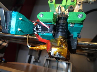
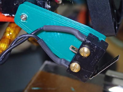
The Z-stop endswitch is then mounted on the arm attached to the servo motor.
The modified extruder and the arm are on thingiverse: http://www.thingiverse.com/thing:193786
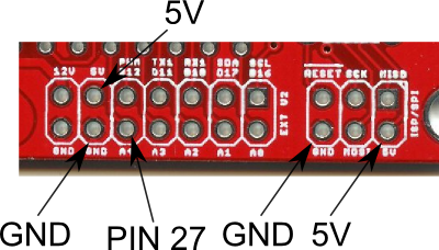
The servo motor needs to be wired to the motherboard. Specifically, it requires 5V power, Ground and a signal pin. In the Sanguinololu motherboard, there are a few possibilities in the extension headers. You can take 5V from any source, and for the signal I used pin 27, shown in the following picture and indicated as A4 on the board (it is the pin below the one used traditionally for the fan):
Part 2: firmware
The firmware needs to be configured for the auto bed leveling feature. Grab the latest snapshot from Adrian's github as described here: http://www.soliforum.com/topic/4236/bet … ll-boards/
NOTE: I don't have experience with Printrboard, so the following instructions are for the Sanguinololu
Assuming that you know how to modify the firmware, open it in your Arduino environment and look for the file pins.h
Navigate to the Sanguinololu section (search for "Sanguinololu pin assignment") and add the following:
#ifdef NUM_SERVOS
   #define SERVO0_PIN 27
#endif
In the Configuration.h file, enable the servo motor by uncommenting the appropriate lines at the end of the file:
#define NUM_SERVOS 1 // Servo index starts with 0 for M280 command
#define SERVO_ENDSTOPS {-1, -1, 0} // Servo index for X, Y, Z. Disable with -1
#define SERVO_ENDSTOP_ANGLES {0,0, 0,0, 165,60} // X,Y,Z Axis Extend and Retract angles
The SERVO_ENDSTOP_ANGLES need to be determined for your setup, so upload the firmware and connect your printer to repetier or pronterface.
Part 3: servo configuration
You will need to determine at which servo angles your Z probe will be extended or retracted. Use the command M280 P0 S{angle} (example: M280 P0 S60 moves the servo to 60º) to test various positions. Write down the angle at which the probe is extended (pointing down) and the angle at which it is out of the way. You might need to rotate the arm with respect to the pivot in order to optimize the travelling range.
Don't worry about the jitter, it will go away in the next step.
Part 4: Second firmware configuration
Change the SERVO_ENDSTOP_ANGLES by writing the two angles that you found in the previous steps as the last pair of values in the curly braces.
Upload the firmware and reconnect the printer.
Part 5: Configuring the bed leveling probe
This is copy-pasted from the Marlin readme:
Next you need to define the Z endstop (probe) offset from hotend. My preferred method:
a) Make a small mark in the bed with a marker/felt-tip pen.
b) Place the hotend tip as exactly as possible on the mark, touching the bed. Raise the hotend 0.1mm (a regular paper thickness) and zero all axis (G92 X0 Y0 Z0);
d) Raise the hotend 10mm (or more) for probe clearance, lower the Z probe (Z-Endstop) with M401 and place it just on that mark by moving X, Y and Z;
e) Lower the Z in 0.1mm steps, with the probe always touching the mark (it may be necessary to adjust X and Y as well) until you hear the "click" meaning the mechanical endstop was trigged. You can confirm with M119;
f) Now you have the probe in the same place as your hotend tip was before. Perform a M114 and write down the values, for example: X:24.3 Y:-31.4 Z:5.1;
g) You can raise the z probe with M402 command;
h) Fill the defines bellow multiplying the values by "-1" (just change the signal)
    #define X_PROBE_OFFSET_FROM_EXTRUDER -24.3
    #define Y_PROBE_OFFSET_FROM_EXTRUDER 31.4
    #define Z_PROBE_OFFSET_FROM_EXTRUDER -5.1
The following options define the probing positions. These are good starting values. I recommend to keep a better clearance from borders in the first run and then make the probes as close as possible to borders:
    #define LEFT_PROBE_BED_POSITION 20
    #define RIGHT_PROBE_BED_POSITION 100
    #define BACK_PROBE_BED_POSITION 130
    #define FRONT_PROBE_BED_POSITION 20
Part 6: Start GCode
You will need to modify your start gcode. Instead of homing the axes, you will now need to probe the bed with the G29 command. This is my code that replaces the first homing commands:
M104 S[first_layer_temperature_0] ;set extruder temp and start heating
G28 X0 Y0 ;home X and Y
G29 ;probe bed
G90; set absolute coordinates
G92 E0; reset extruder distance
G1 Z5 F300 ;move platform down 5mm
G1 X145 Y145 F3000 ; move to back right corner
The probing settings seem to be reset once you home the axes, so be careful with the homing button.
Note
Backlash is not your friend. Try to minimize it as much as possible. I succesfully used the Hysteresis fix to remove a bit of residual backlash in the Z direction.
I know this is a long guide, but I assure you it's worth it! If you have any question just ask. And I would be grateful if someone with a Printrboard could give some insight on its configuration.


