1

Topic: My self-made FreeLSS Scanner Project

Hello all,
My name is Adam, my job is putting 3D printers and laser engravers to work, and I figured a 3D scanner would be a boon to my livelihood.  Found FreeLSS and the Atlas files on Thingiverse, decided to try it out, didn't really like the sheer number of individual parts in it.  I have most of the electronics and hardware lying around anyway, so I popped open my CAD software and designed my own chassis.

Tried out V1 today, found the blue camera issue and got the pin assignments sorted out, so I've got the lasers blinking and the turntable turning.

I initially set out to 3D print the chassis, but ended up laser cutting the bulk of it out of wood.  I initially went with a wooden laser/camera tower but I'm switching over to a 3D printed tower to increase stability, rigidity, add some points of articulation, make sure it doesn't curl in the humidity, etc.  Should also increase takeapartability.

I made some educated guesses on size.  I went for 250mm horizontal from table to lens, and close to that for laser to laser.  Camera height is approximately 60mm above the bed, I'm probably going to raise it.  These sound sane?

Pictures to come eventually.

2

Re: My self-made FreeLSS Scanner Project

Work begins on V2.  The wooden tower didn't give men enough articulation on the camera, so I've gone to a system similar to what's on the ATLAS.  The camera clamp also holds the laser arms.

I'm going to have to redo the wooden box, as it is too short.  The camera is too close to the turntable, it got closer by nearly 3cm when I swapped to the plastic tower.

I'm also getting something odd, my lasers are kind of blinking.  I think they're good enough, but we'll see.  I also get a hellacious noise from the stepper driver, I think I'm going to have to up the capacitance there.

Image below, if you can abide my hideously messy desk.

http://soliforum.com/i/?jEBPZkQ.jpg

3

Re: My self-made FreeLSS Scanner Project

What do I do if I get a hopeless cloud of dots out of it instead of something that looks even vaguely like the scanned object?

4

Re: My self-made FreeLSS Scanner Project

Check your measurements on everything. I made my own that is mostly 3D printed other than threaded rod and some conduit. I went mostly by the ciclop bom and assembly instructions for rod lengths and my conduit length, combined with some math from the stl files for piclop on thingiverse. By looking at where they connected the rods to the peices and how things overlapped on the laser parts I calculated the width of the spread between my tower and laser mounts and from my tower to my turntable.

The ciclop bom with rod lengths are here: http://diwo.bq.com/en/ciclop-released-2/

The piclop stls are here: http://www.thingiverse.com/thing:754003

There is no need to be 100% perfect since you can adjust the values in the software. There is a helpful diagram for setup on this post: http://www.soliforum.com/topic/13250/fr … arameters/

My guess would be that you have the dimensions out of whack and it's confused. The first test scan I did came out pretty good for having no idea what I was doing. Did you have good scans with your original design and now they are messed up or dos you not try the original design before printing the new one?

5

Re: My self-made FreeLSS Scanner Project

av8r1 wrote:

What do I do if I get a hopeless cloud of dots out of it instead of something that looks even vaguely like the scanned object?

Can you post an image of your scan results?  I agree with Dali01...check your measurements.  Also, ensure your laser and camera alignments are good.

I've had occasions where either the lighting was too bright, or the scanned object too reflective, which caused a lot of scattered points.

6

Re: My self-made FreeLSS Scanner Project

I'm amazed people who even bought the kit have gotten this to work.  Meaningful documentation is thinner on the ground than women worth dating.  I'm sick of writing manuals for people because they can't be bothered.

What does the "calibrate lasers" button do?

The camera view has two crossed red lines, and a little tick mark on the vertical line near the bottom.  What is it's purpose?  Is that "zero?"  How am I supposed to interact with that?

When you click "test" and it gives you "5.png" what are you supposed to do with that information?  There's a blue vertical line, some red pixels I assume are supposed to be the lasers, and some green and yellow crosshairs.  What exactly do those crosshairs mean, and which color is for which laser?

Why can I get it lined up well in one camera mode, and then it's out of alignment again in another camera mode?  Is that feature useless?

I've been trying to scan a yellow spherical smiley face.  The machine seems to struggle with any color darker than bright yellow unless it's in full darkness.  This happened:  http://soliforum.com/i/?EZkiBrQ.png

I work in 3D printing, it would be a boon to my business to be able to scan small objects.  Can this reliably do that?  If not (which I'm imagining is the case) what can?

7 (edited by knowack 2017-03-05 19:19:08)

Re: My self-made FreeLSS Scanner Project

Those are all good questions. You first need to calibrate your scanner, before expecting to achieve good results.

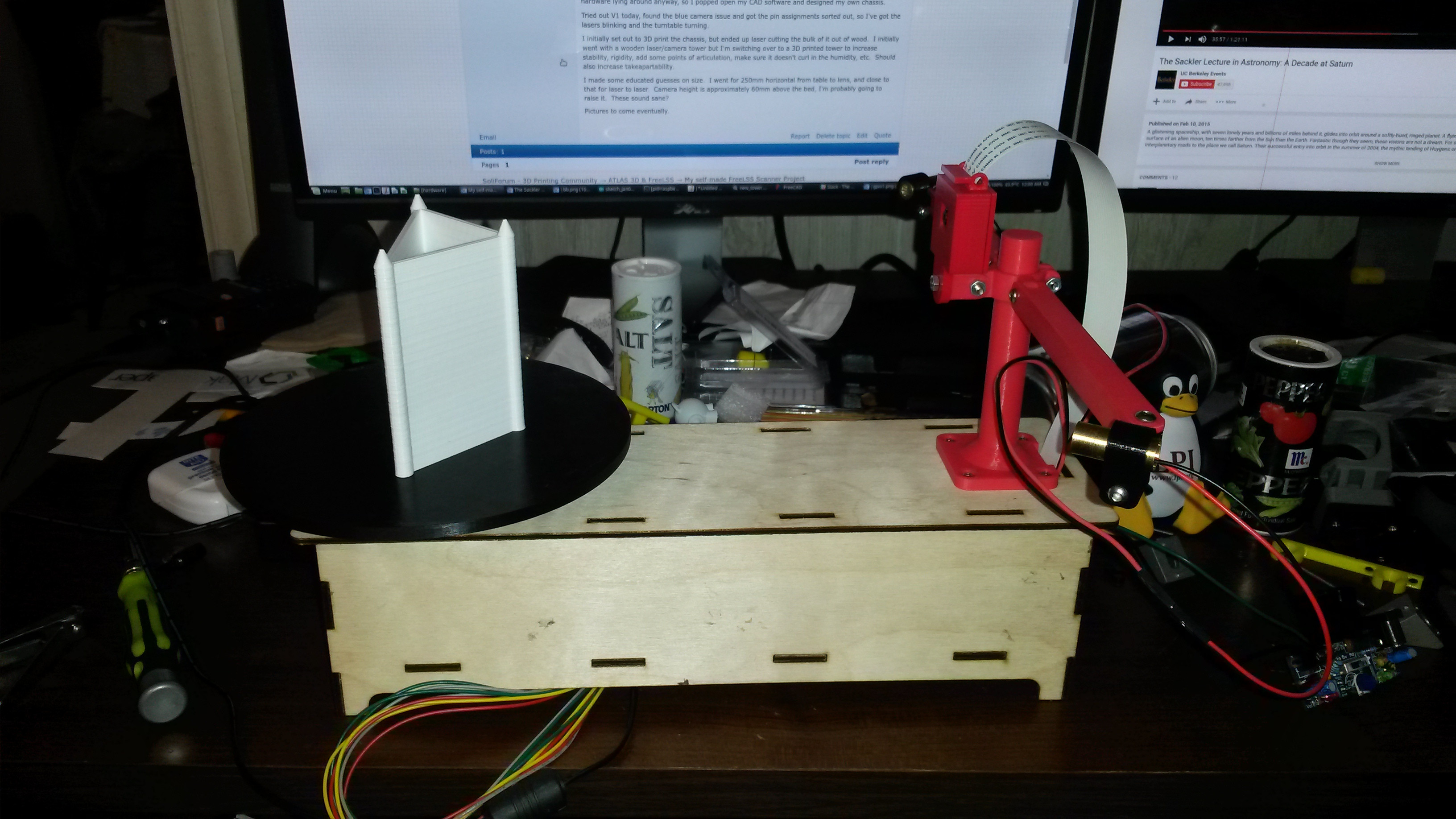
I will also try to find something spherical to scan.

I'm going from memory here, but the documentation points you to the ATLAS 3D & FreeLSS topics in this forum.  There are Welcome, Calibration, Instructions, and Troubleshooting topics that are sticky at the top of the list.  They will answer all your questions in detail, but I will give you an overview:

In camera view, the horizontal mark at the bottom of the crossed red lines show where the camera is supposed to see the center of the turntable.  The larger crossed lines are used to help align the camera in the vertical and horizontal planes.  If your camera is not aligned correctly, you will not get good geometry to your scans.

The 'test' generates a .png file to show you how well the camera is detecting the lasers as they strike the target object.  This is used to select the best settings for your object and lighting environment.

Once you've done the best physical alignment of the lasers possible, the 'calibrate lasers' option will look at the lasers and calculate a software correction for further compensation.  The calibrate feature only works in hi-res camera modes.  Calibration stays true between all camera modes; if it is not, then most likely the calibration is not yet optimal.

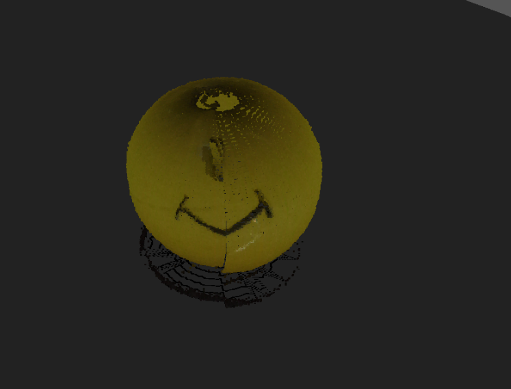
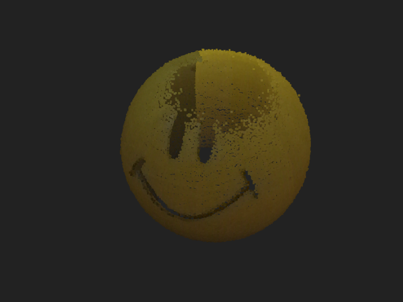
When completed, the results are quite good.  You cannot expect satisfactory results from any 3D scanner, if it is not properly calibrated.  As I have mentioned elsewhere, I've used a Matter and Form (commercially produced) scanner in the past, and the Altas3D does a better job. 

If you're having trouble with color, use different lighting.  LED lighting is problematic, since a white LED is actually a blue or UV LED whose output is jinked by phosphor. Even though our eyes see a relatively white color, depending on whether the phosphor is being excited by blue or UV, there is a resultant color shift that digital cameras can detect.  Halogen lighting also looks good to our eyes, but digital cameras seem to detect a yellowish hue from that lighting.  In my experience, incandescent lighting works best, and you may have to play around with a few types (e.g. cool white, soft white, Reveal) to find what works best for you.  I've also found that 'over-illuminating' the scanning target causes as many problems as 'under-illuminating' it.

A final thing to note is that any 3D scanner works best when the camera can see a sharp laser strike upon the target object.  A reflective object needs to be 'dulled down' with powder in order to capture the laser.  For example, a glass mug does not scan well, since the vast majority of the laser energy will either be reflected off the surface, or transmitted on through the structure.  When I scan matchbox cars, I simply powder them to overcome the glossy paint, and define the clear plastic windows.

The opposite of gloss is an object that absorbs and diffuses the laser.  Some types of plastic are bad for this (3D printed objects can be terrible to 3D scan).  Plaster casts are also poor targets due to their porous and grainy surface; I paint such object in a neutral gray before scanning. Black objects absorb the laser energy, and need to be powdered.  Of course, a tennis ball would be terrible to scan, due to the fibrous texture of its surface. 

Using the 'test' feature to view the laser detection upon object can aid you in deciding if powder or paint could help to better define the laser line.

I hope this helps, but you really need to look at the documentation.  Calibrate.  Illuminate.  Scan.

8

Re: My self-made FreeLSS Scanner Project

I found a glossy golf ball to scan.  I intentionally 'over-illuminated' it, and didn't use powder on it.  This left the top undetected, and allows us to look down through the top to see the geometry:

https://www.dropbox.com/s/zgru5zsmra0tr19/Golf%20ball.PNG?dl=1

This was scanned using the 'Default' profile, except that I'm using both lasers.  You can see that the Atlas3D picked up the dimples quite well, and the overall geometry is perfectly round.  This illustrates the need for proper laser and camera calibration to achieve good results.

If you look at the spider-web effect in the center, that is where the software applied geometry to the bottom that it couldn't actually see.  I didn't quite get the ball centered on the turntable, as evidenced by the fact that the center of the spider-web is up and slightly left of the image center.  This shows that the objects don't have to be exactly centered for good results, but the camera must be for the geometry to meet.

9

Re: My self-made FreeLSS Scanner Project

I'm not worried about color fidelity, just contour.  For example, by turning out all my lights, I was able to get a scan of a little Tux doll I have here.  Being a penguin he's mostly black except his face, feet and belly, and if there was any light in the house that's all the scanner would capture.  If I can either chalk paint him white all over or turn out the lights and capture only the laser lines, that's fine.  That would let me 3D print a copy.
I have existing and potential customers looking for this service.  For instance, a customer brought me a palm-sized motorcycle fairing part and asked me to duplicate and mirror it (it's twin on the other side of the bike blew off in the wind, this bike was made 20 years ago in small numbers, so parts are unobtainium.)  It's a black chunk of plastic.  The company I work for has a 3D scanner, but it doesn't work for items much smaller than a cubic foot.  I'm looking to plug that gap.
I've been using the triangular-with-three-points-on-top style of calibration item.  Do I need to make a grid or that crosshair plate?

10

Re: My self-made FreeLSS Scanner Project

A few changes I'm thinking of making: I could hinge the laser arms forward (they're perpendicular to the "spine" of the machine at the moment) to bring them closer to the object so they shine a more intense light on it.  I may also raise them and angle them downward so that they shine more definitely on the top of the object, and I might raise the camera so it can see the top of the object better.
It may require placing the camera and even the lasers on adjuster springs.  I can do that, but it would be tedious.

11

Re: My self-made FreeLSS Scanner Project

The scan using one laser:http://soliforum.com/i/?A5zSuUU.png

Note the eyes and mouth are open.  They're black paint on the original.  I guess the black paint absorbs too much red laser light for the camera to notice, so it thinks there's nothing there.
It does this for blue objects as well.

12

Re: My self-made FreeLSS Scanner Project

I know all about unobtainium!  I have two old Super Beetle convertibles, an Alfa Romeo Spider, and old motorcycles that I'm always 3D printing parts for!  It's the little stuff that's getting harder and harder to find.

The calibration item I use came with the laser-cut acrylic frame:
https://www.dropbox.com/s/6nhlcz5uy6cjet1/calibration%20tool.PNG?dl=1

Look at this Youtube video about 50 seconds in:
https://www.youtube.com/watch?v=vvfXvUgtoUg

There's probably a file on the internet somewhere to laser-cut your own.

You're exactly right about the black paint...it's absorbing the laser.  Brush on a little talcum powder (it doesn't take much), and the laser will be detected.  Instead of messing with laser intensity, play with laser detection.  You can set 'Image Threshold Mode' and 'Laser Threshold' on the settings page.  You will probably want to adjust your 'Noise Removal' when playing with the detection settings.

Instead of altering the geometry of your Atlas3D, consider trying something I used to do with the Matter and Form scanner:  I would scan an item upright, then scan it laying on its side (to capture the top and bottom).  I'd combine the point clouds together in MeshLab.  (The Matter and Form software had a 'combine' feature, but it never worked. 

I would be afraid that I'd become 'lost in space' trying to re-arrange the hardware, then fiddling with the X Y Z parameters of the camera and lasers.

The M and F has a motorized Z-height threaded shaft for the camera.  It would do a complete 360° scan, then raise the camera and do another 360°.  It was handy for taller objects, but I feel the overall accuracy suffered due to the extra mechanical movement.  I'm not sure it was worth the effort.

13

Re: My self-made FreeLSS Scanner Project

@knowack I can easily CAD that up myself, all I need to know is how far the horizontal line needs to be from the bottom edge.  Desired lens height above bed level?

14 (edited by dali01 2017-03-06 05:42:11)

Re: My self-made FreeLSS Scanner Project

I agree on te documentation. It is sparse and highly spread out over various pages that are extremely difficult to find. I don't know if you found this page or not, but it explains a lot of that:

https://www.murobo.com/start.html


Edit: I am using the calibration card and stand from the ciclop page I posted in my prior post.

15

Re: My self-made FreeLSS Scanner Project

Another hint:  Make sure the bed is secure to the motor shaft.  Mine came loose. Now why wouldn't it be making a full revolution I wonder?

16

Re: My self-made FreeLSS Scanner Project

The motor on my machine is getting quite hot.  I've set the driver current but it's still up there in temperature.  I think what I'll do is revise my motor mount so that the motor can physically touch the 2020 beam (I abandoned the above wooden box above) and use the chassis as a heat sink.

17

Re: My self-made FreeLSS Scanner Project

http://soliforum.com/i/?BHx3n9Z.jpgplease, could you help e to find a solution for this error

18

Re: My self-made FreeLSS Scanner Project

You are missing libiw-dev.  Please make sure you follow all of the instructions in the COMPILE section on https://github.com/hairu/freelss

- Uriah